C. For a VA-1A-XX (external shunt unit), connect both shunt leads (orange and brown) to the bus
or one side of the shunt. The unit must read 00.0 (+/- 0.3) Amps. A poor connection in the
orange or brown lead will cause only the Amps reading to wander around. Check for poor
connections (pull on each wire at the back of its connector). Check the fuses and fuse holders.
Check that the signal shunt leads do not supply power to any other piece of equipment.
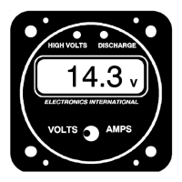
3. Discharge Warning Light Works Incorrectly
Check that the 12/24 Volt Select Switch on the back of the unit is set properly. The Discharge
Warning Light will be on when the bus voltage (on the Red wire) drops below 12.6 volts (25.2 volts
for a 24-volt system).
4. High Volts Warning Light Works Incorrectly
Check that the 12/24 Volt Select Switch on the back of the unit is set properly. The High Volts
Warning Light will be on when the bus voltage (on the Red wire) exceeds 15.3 volts (30.6 volts for
a 24-volt system).
5. Back Light Works Incorrectly
On a 12-volt system, the 24 volt line must be grounded. See the Wiring Diagram. Check for poor
connection on the backlight wires (white/brown and white/red).
6. Bench Test the Instrument
To bench test the VA-1A or the VA-1A-XX connect one lead of the internal shunt (or both the
orange and brown leads for the VA-1A-XX) to the red lead and connect all of them to a power
supply (7 to 40 volts). Connect the black lead to ground. The unit must read 00.0 (+/- 0.3) Amps
and proper voltage.
Troubleshooting
15