each wire and double the wires over. Doubling the wires over and a good tight crimp are critical
for a good reliable connections.
Connect the VA-1A-XX instrument wires to the RSVA-3 harness wires.
5. Install the RSVA-3 in the Panel
The RSVA-3 requires a 1" x 1" square mounting hole. Install the RSVA-3 switch from behind the
instrument panel using the screws and nuts provided in the RSVA-3 kit. Push the two mating
connectors of the RSVA-3 and its harness together and twist until they snap into position. Turn
the locking ring onf the RSVA-3 connector clockwise (1 1/2 turns) until it locks into position. Tie
wrap the harness making sure these wires do not obstruct the freedom of travel of any controls.
6. Ground Test
RSVA-3 in the Battery PositionRSVA-3 in the Battery Position
RSVA-3 in the Battery PositionRSVA-3 in the Battery Position
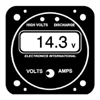
RSVA-3 in the Battery Position - With the master on and the engine off, the discharge light on
the VA-1A-XX should be on, the Volts position will read 11.9 to 12.5 volts (23.8 to 25 volts for a
24 volt system) and the Amps position should read -2.0 to -10.0 amps depending on your current
load for the aircraft. Changing the load will change the amps reading.
With the master on and the engine on, all lights on the VA-1A-XX will be off, the Volts position will
read 13.2 to 14.8 volts (26.4 to 29.6 for a 24 volt system) and the Amps position will read 5.0 to
15.0 amps and reducing rapidly (shows batter changing current). Changing the load will not
change the amps reading. See the operating section of this manual for futher details.
RSVA-3 in the Left or Right Alternator PositionRSVA-3 in the Left or Right Alternator Position
RSVA-3 in the Left or Right Alternator PositionRSVA-3 in the Left or Right Alternator Position
RSVA-3 in the Left or Right Alternator Position - With the master on and the engine off,
the discharging light on the VA-1A-XX instrument will be on, the Volts position will read 11.9 to
12.5 volts (23.8 to 25 volts for a 24 volt system) and the Amps position should read 0.0 amps +/-
0.3 amps. Changing the load will not change the amps reading.
With the master on and the engine on, all lights on the VA-1A-XX will be off, the Volts position will
read 13.2 to 14.8 volts (26.4 to 29.6 for a 24 volt system) and the Amps position will read 5.0 to
25.0 amps and reducing rapidly (shows battery charging current plus load current for the air-
craft). Changing the load will change the amps reading. See the operating section of this manual
for futher details.
20
RSVA-3 Installation Instructions 5. Install the RSVA-3 in the Panel