C. If this piece of electrical equipment is working properly, you will see an increase in load
current that corresponds to the current that piece of equipment requires. Compare this
current with the current you measured for that same piece of equipment at an earlier date.
Using this method with the digital display of the VA-1A, many important aircraft functions
(strobes, retracts, radios, transponder, ADFs, DMEs, pitot heat, etc.) can be checked from the
pilot’s seat. It would be worthwhile to write down the load current for the entire system and for
each piece of equipment. This would give you something to compare to when you wish to check for
proper operation at a later date. You may also check the entire electrical system with one check
by turning all the electrical equipment on and comparing the amps reading with your normal
reading taken at an earlier date. If an improper reading is noted, the VA-1A may then be used to
diagnose which piece of equipment has malfunctioned by checking each piece of equipment sepa-
rately.
With the mode select switch in the “Volts” position, the VA-1A will display the bus voltage to 0.1
volts. With all electrical equipment off and a fully charged battery the bus voltage will be around
12.1 to 12.5 volts (double these levels for a 24-volt system). Each battery has its own operating
voltage when charged. As the battery gets near the end of its life, this voltage will start to drop. A
discharged battery will also run at a lower voltage. Don’t confuse a good discharged battery with
an old battery.
2. Master On, Engine On
The following describes the operating characteristics of the VA-1A installed in the battery lead
with the master switch on and the engine on.
With the Mode Switch in the “Amps” position, the VA-1A will display the charging current to the
battery. When the engine is first started, the current will jump up to 20 amps or more and will
quickly decrease as the battery takes a charge. Within a few minutes, the charging current will
have dropped to 6 amps or lower and will continue to drop for the next hour until it settles to 1.0
amps or lower.
With the VA-1A installed in the battery lead, load current cannot be monitored during flight. The
Alternator (or generator) is supplying all of the electrical load and charging the battery. Only the
battery charging current can be monitored for this installation.
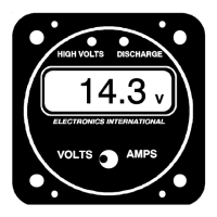
With the mode selector switch in the “Volts” position the VA-1A will display the bus voltage to 0.1
volts. With the engine running the alternator is capable of raising the bus voltage to a danger-
ously high level. It is the voltage regulator's job to limit the bus voltage between 13.5 and 14.8
volts (double these levels for a 24-volt system). Look for this level on the VA-1A. A low voltage
reading will cause the battery to charge very slowly. A high reading can damage the battery and
most of your electrical equipment. If the aircraft bus voltage goes to a dangerously high level
(15.3 volts or higher) a bright red “High Volts” light on the VA-1A will warn you of this condition.
If this happens turn the field to the alternator off to eliminate the over voltage condition.
5
Operating Instructions VA-1A Installed in the Battery Lead