6
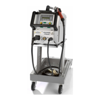
Torch connection
Plug in the centralplug 17 of the torch 1 into the central socket
16. At machines with water-cooling: Connect additionally the
waterconnections 20 of the torch with the sockets 18 and 19.
Please keep attention at the colour labelling.
Red = water back-run 19
Blue = water fore-run 18
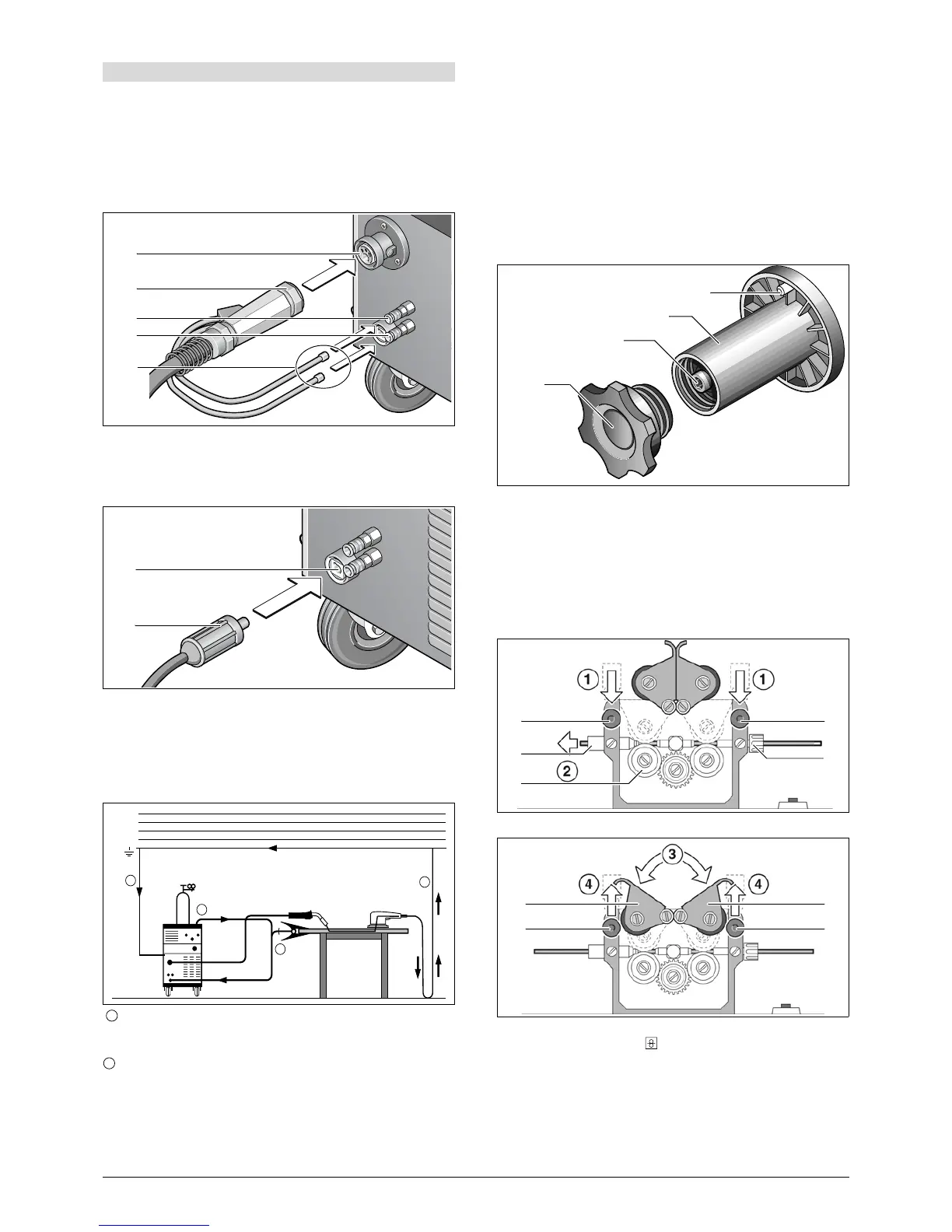
How to connect the ground cable
Connect the ground cable 22 at the groundconnection 14 and
fasten it turning to right and connect the ground clamp 13 to
the workpiece or at the welding table.
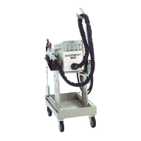
How to connect the ground clamp
Fasten the ground clamp 13 near the welding location, this
avoids that the current will flow trough machineparts or con
-
trols.
Please keep attention that the connections between ground
clamp and workpiece is constant.
Do not place the ground clamp on the welding machine or
gas cylinder, otherwise welding current is conducted via
the protective conductors and will destroy them.
Connect the ground clamp tightly to the welding bench or
to the workpiece.
How to connect at the mains
Plug in the plug into the mains socket. The fusing should be
corresponding to the technical data.
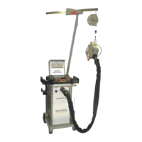
How to insert the wirespool
Open the lid at the machine or at the wire-feed case 2 and
screw off the nut 26 from the wire-coil pick-up 24.
Put on the wire coil at the wire-coil pick-up and pay attention
that the tappet is well insert at the coil 23.
By use of small wire coils please use the adapter.
Adjust the brake 25 by releasing the torch button the wire coil
do not continue to turn.
Insert of the wire electrode
Screw out the contact tip at the torch 1.
Open the lid at the unit or at the wire feeder 2.
The diameter of the wire should correspond to the diameter of
the feeding rolls. This is readable on the front at the built in
feeding roll 29.
Lift the lever 27 and thread in the wire electrode trough the in-
let nozzle 28 and the central connection 16.
Close the lever 30 and fasten it with the sweep levers 27.
Switch on machine at main switch 11, stretch torch cable and
press button wire insert
on operating panel. Adjust the
pressure at the modulation screws 27 that the wire-feed rolls
29 even still are turning by holding the wire coil. The wire
should not be clamped or deformed.
10 Before operation
16
17
18
19
20
14
22
2
1
1
L
1
(R)
L
2
(S)
L
3
(T)
N(MP)
PE
1
1
2
23
24
25
26
29
27
28
16
27
30 30
27
27