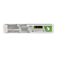
6 How to active
How to active
6.1 Antenna connection
To connect the RF output connector to the antenna cable (to test the performance of the
apparatus can be connected to a dummy load capable to consume the power supplied
from the apparatus).
6.2 Essential connections to operation
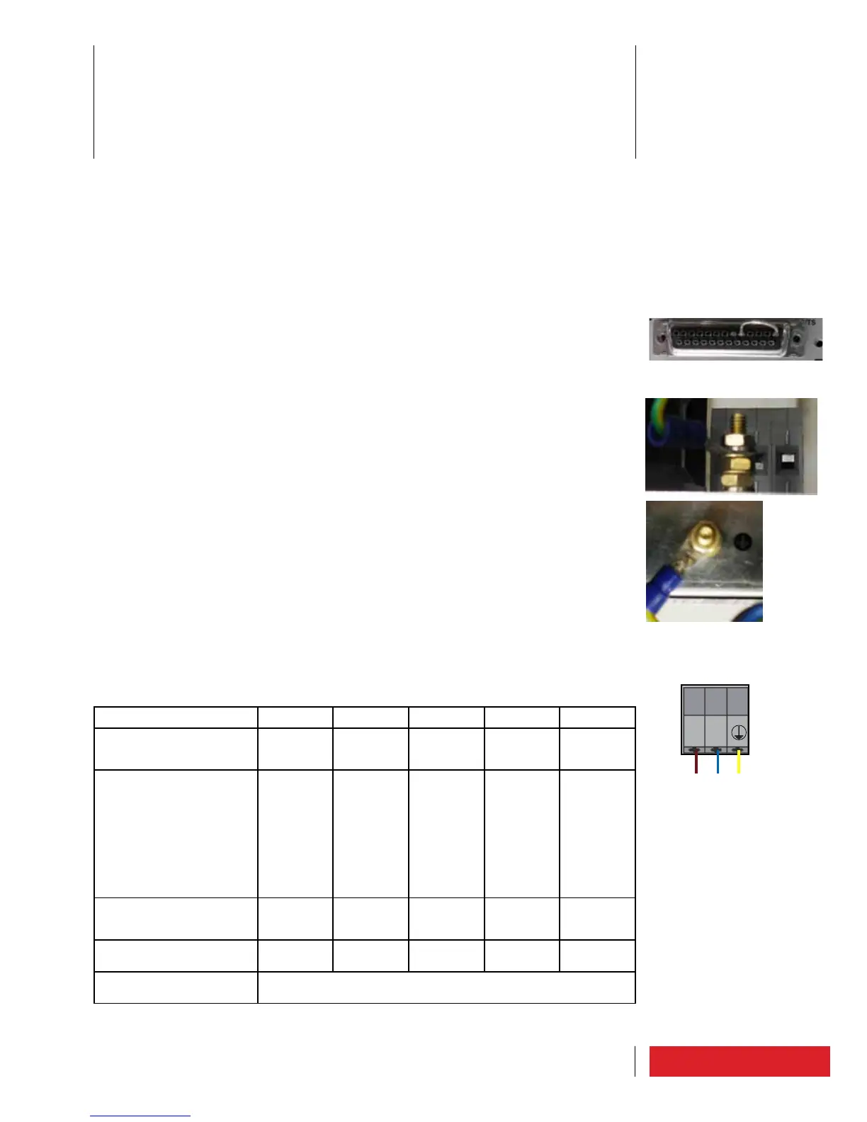
In case of option TC/TS, to check for the interlock jumper (fig.a).
6.3 Mains connection/disconnection
To be sure of the proper grounding to be made at the screw located below the supply
terminals and/or to the terminal referenced by the ground symbol (fig.b1-b2-c1).
The apparatus is designed for single-phase (two-phase) 230VAC power. Where the po-
wer supply is single-phase 115VAC, the guaranteed maximum power can be reduced in
accordance with what shown in the table below.
WARNING: to connect the power cord to the terminals of the apparatus, to be sure
that the cord is DISCONNECTED from the mains, or strictly unpowered.
First verify that the available power supply is adequate, then apply the conductors of
phase and neutral (or phase1 and phase2) to the supply terminals (fig.c1).
WARNING: if you need to disconnect the equipment to do backwards, always first
disconnecting the plug from the mains and then removing the wires from the
terminals.
To use appropriate cables, according to the installation parameters as specified below:
ETG1600.3 ETG1200.2 ETG800.1 ETG150 ETG30
Typical consumption at
rated power @ 230VAC
single-phase / two-phase
2.2KW 1.7KW 1.15KW 300W 60W
Typical consumption at
rated power @ 115VAC
single-phase
50% of
consum-
ption
@230VAC,
since the
RF power
provided
@115VAC
is 50%
lower that
@230VAC
50% of
consum-
ption
@230VAC,
since the
RF power
provided
@115VAC
is 50%
lower that
@230VAC
1.15KW 300W 60W
Typical current absorption
@ 230VAC single-phase/
two-phase
9.6A 7.4A 5A 1.3A 0.3A
Typical current absorption
@ 115VAC single-phase
9.6A 7.4A 10A 2.6A 0.6A
Cable cross section (mini-
mum recommended)
2.5mmq (13AWG)