22
1 4
2
8
7 6 5 3
8
7
5
6
Product description
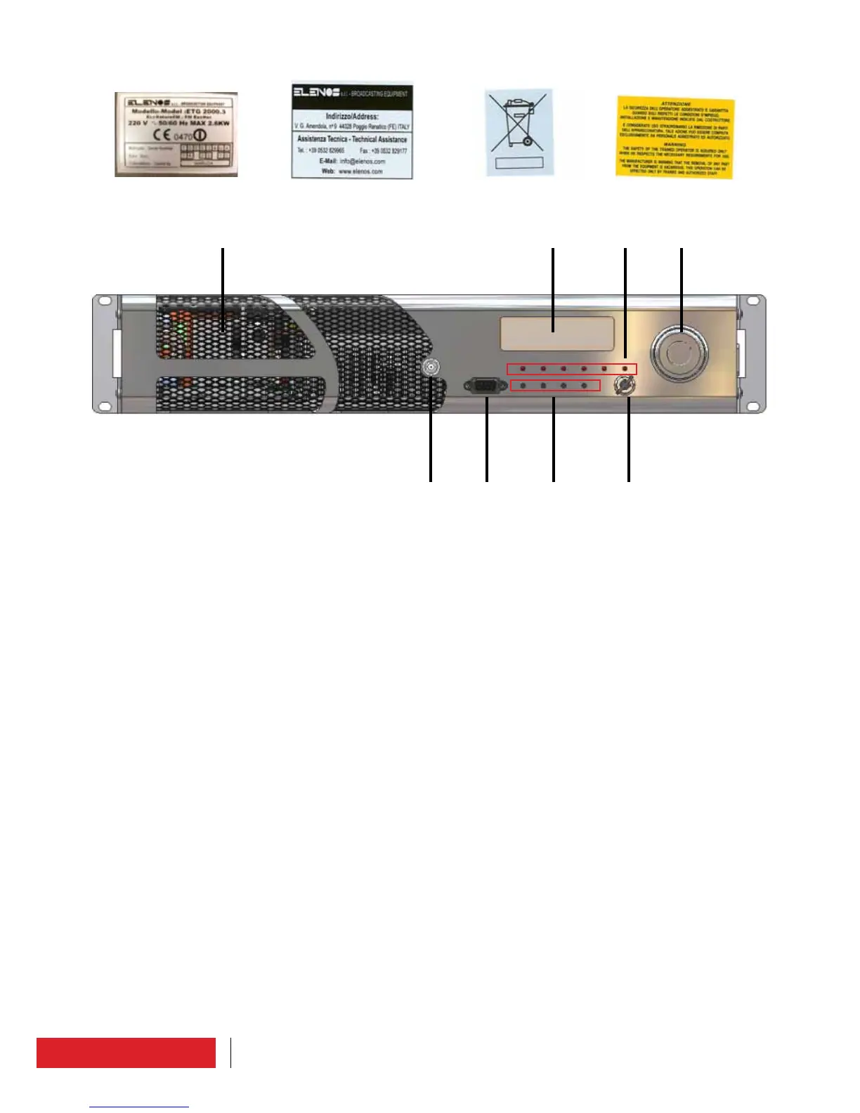
5.2 Front panel
1 OLED display – graphic display that shows operative parameters and functions selec-
ted by encoder.
2 Encoder – multi-function knob that allows to see functions menu and to modify opera-
tive parameters:
• SELECT HIGHLIGHTED ITEM_short pressure of the knob;
• SCROLL ITEM_rotation of the knob clockwise / counterclockwise;
• INCREASE / DECREASE_rotation of the knob clockwise / counterclockwise;
• RETURN TO MAIN MENU_long pressure of the knob (at least 1 second).
3 Keyswitch – by rotating the key supplied with the apparatus. It can be placed in LOCAL
mode (front panel-manageable) or REMOTE mode (PC-manageable).
4 Leds – leds list :
• MAINS (green) _ it is on and fixed in the presence of power supply;
• ST-BY (yellow) _ it is on when the transmitter is is in stand-by;
• ON AIR (green) _ it is on when the transmitter is on air;
• PLL LOCK (yellow) _ it is on when the PLL is locked;
• FAULT (red) _ it is on when the transmitter is in a fault condition;
• LOCAL (blue) _ it is on if the tansmitter is in local mode.
5
Button/Command – button list :
• LIFEXTENDER;
• OFF _ through this button the user can put in stan-by the transmitter;
• ON _ through this button the user can put on air the transmitter;
• ESC _ Escape button, back to main menù.
6
Interface connector – DB9 connector, to connect a telemetry or a PC, according to