
П
ПавелSep 24, 2025
Где взять софт для настройки частоты через RS-232???
Где взять софт для настройки частоты через RS-232???
Defines operational responsibilities, qualifications, and safety awareness for personnel.
Groups responsibility, warranty terms, and legal jurisdiction for product use and disputes.
Lists essential safety measures to prevent electrical and operational hazards.
Provides guidance for immediate medical assistance in case of electrical burns or shocks.
Describes environmental and wiring requirements for safe equipment operation.
Describes the product's purpose, operational band, and key features.
Groups shipment, unpacking, storage conditions, and disposal procedures.
Details checks required upon receiving the product for completeness and damage.
Identifies and explains the various labels on the device, including warnings and service info.
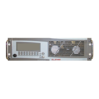
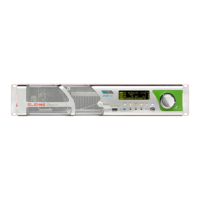
Details the controls, display, and indicators on the front of the unit.
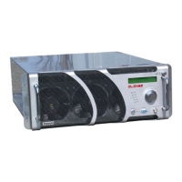
Describes the connectors and components located on the rear of the unit.
Introduces the detailed description of all external connectors on the device.
Describes the interface connector for PC communication and telemetry.
Groups MPX, Stereo, Mono, AUX, and AES/EBU audio input connectors.
Describes output monitoring, 19kHz, and TC/TS telecontrol connectors.
Details the connector for system profile management and configuration.
Describes network (TCP/IP) and telemetry (EIA485) connectors.
Contains detailed technical specifications, performance data, and environmental requirements.
Explains the integrated hardware and software protection systems of the device.
Details intelligent software protection algorithms like IPF, IPC, and Safety Management.
Lists the physical protection mechanisms against faults, like fuses and VSWR.
Describes the optional features that can be purchased with the transmitter.
Instructions for connecting the RF output to the antenna or a dummy load.
Notes on critical connections like the interlock jumper for TC/TS option.
Details on properly connecting and disconnecting the power supply, including grounding.
Lists the default configuration parameters of the device as shipped from the factory.
Explains how to adjust key operational parameters like frequency, power, and audio.
Step-by-step guide to setting the operating frequency using the encoder.
Instructions for adjusting the output power level via the device interface.
Details on adjusting the audio input levels for optimal modulation.
Covers the selection of various audio input types like MPX, Stereo, Mono, AES/EBU.
Guides the final activation of the unit and checking status indicators.
Explains navigation and interaction with the device's menus and settings.
Describes the main display and basic parameter modification window.
Groups Audio Setting, Levels, and Input type selection for audio setup.
Groups View/Setting and Temperatures for monitoring system status.
Lists active and historical alarms with details and status.
Logs system events, including alarms, with timestamps for tracking.
Displays temperatures and currents for individual RF modules.
Shows status information for the power supply units (PSUs).
Adjusts pilot tone parameters for stereo modulation.
Displays saved configuration profiles, including frequency, power, and audio settings.
Control menu (read-only) related to the preamplifier settings.
Groups Voltages, System Info, and System Time displays.
Allows scheduling power output over time using time slots.
Sets the limit for reflected power to protect the transmitter.
Manages user and system passwords for accessing device settings.
Procedure for recovering forgotten passwords via Elenos support.
Enables and configures foldback protection against VSWR issues.
Configures SMS alerts for alarms and custom alarm conditions.
Displays status information for serial communication ports (Uart 0, 1, 2).
Provides a comprehensive list of all possible alarms and their descriptions.
Lists SMS commands and status message formats for remote control.
Describes connections for external units like PCs, telemetry, and audio matrix.
Setup for remote PC control and parameter adjustment via HyperTerminal.
Setup for telemetry units and exchange units for system redundancy.
Details connecting to external RF power amplifiers for increased output power.
Lists available components for replacement, categorized by part number.
Outlines a periodic maintenance schedule for cleaning, checks, and filter replacement.
Describes common problems, their causes, and suggested solutions.
| Frequency Range | 87.5 MHz to 108 MHz |
|---|---|
| Modulation | FM |
| RF Output Impedance | 50 Ω |
| AC Input Voltage | 100 - 240 VAC, 50/60 Hz |
| Dimensions | Variable depending on model |
| Weight | Variable depending on model |