12
3
1
2
1
2
Product description
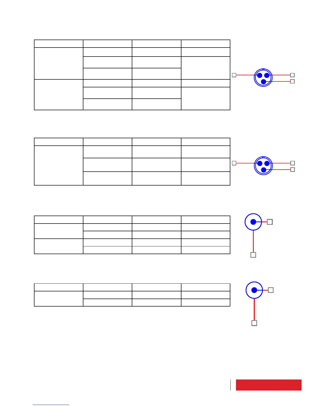
5.4.2 LEFT/RIGHT connectors
N° 5 Rear panel (XLR Female)
Connector Pin Description Note
J01 on board TG-
3K1A866 or J1 on
board TG3K2A867
1 Common ground
2 Audio signal right
channel “+”
Differential input
3 Audio signal right
channel “-”
J02 on board TG-
3K1A866 or J2 on
board TG3K2A867
1 Common ground
2 Audio signal left
channel “+”
Differential input
3 Audio signal left
channel “-”
5.4.3 AES/EBU connector
N° 6 Rear panel (XLR Female)
Connector Pin Description Note
J3 on board TG-
3K2A867
1 Common ground
2 Input-differential
“positive” AES EBU
3 Input-differential
“negative” AES EBU
5.4.4 AUX connectors
N° 7 Rear panel (BNC Female)
Connector Pin Description Note
J2 on board TG-
3K0A866
1 RDS/SCA AUX1 Input
2 Common ground
J3 on board TG-
3K0A866
1 AUX3 Input
2 Common ground
5.4.5 MPX connector
N° 8 Rear panel (BNC Female)
Connector Pin Description Note
J1 on board TG-
3K0A866
1 External MPX Input
2 Common ground
 Loading...