1
2
Product description
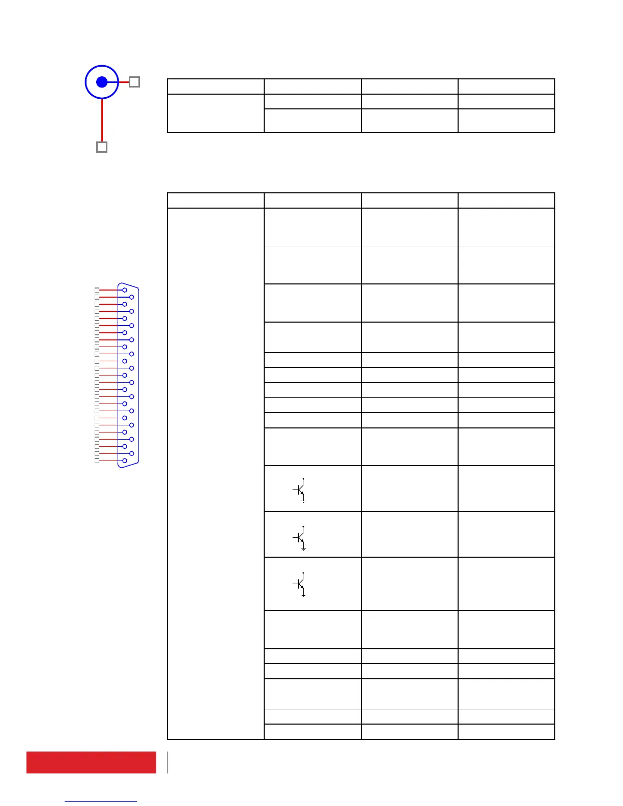
5.4.6 Monitor/19kHz connector
N° 9 Rear panel (BNC Female)
Connector Pin Description Note
J4 on board TG-
3K0A866
1 Monitor MPX-19KHz Output
2 Common ground
5.4.7 TC/TS connector (option)
N° 10 Rear panel (DB25 Female)
Connector Pin Description Note
CN1 on board
TG2U1A899
(Signals compatible
with IEC 60864-1
standard)
1 F_TC_INTRLCK Interlock (Enable)
Pin connected to
ground = command
active
2 F_TC_TX_ON TX ON
Pin connected to
ground = command
active
3 F_TC_TX_OFF TX OFF
Pin connected to
ground = command
active
4 F_DTM_REFL_PWR Analog voltage output
reflected power (see
5.4.7.1 paragraph)
5 Common ground
6 F_RX- EIA485
7 - No connected
8 F_TX- EIA485
9 Common ground
10 F_DTM_I_PA Analog voltage
output current Power
Amplifier (see 5.4.7.1
paragraph)
11 F_TS_/FLT_MAIN FAULT status mains
Pin must be exter-
nally powered.
“Open” status →
Fault active
12 F_TS_TX_ON TX ON status
Pin must be exter-
nally powered.
“Closed to ground”
status → TX ON
13 F_TS_WARNING Warning
Pin must be exter-
nally powered.
“Closed to ground”
status → Warning
active
14 F_TC_ALRM_RST Reset allarms
Pin connected to
ground = command
active
15 - Spare pin
16 - Reserved Elenos
17 F_DTM_FWD_PWR Analog voltage output
direct power (see
5.4.7.1 paragraph)
18 Common ground
19 F_RX+ EIA485
open collector
open collector
open collector