20
Installation
4.4 Setting the electronic limit switches
CAUTION
Damage to the device due to a voltage failure during the programming proce-
dure.
•
After a voltage failure during programming, check whether the limit positions
have been deleted.
The electronic limit switch is integrated into the drive.
The device has non-adjustable absolute limit positions that have been program-
med at the factory.
These are programmed to the designed stroke of the device. The electronic
non-adjustable safety limit switches, which can only be reached in the event of
a defect and which therefore switch off the device, are located a short distance
behind these absolute limit positions.
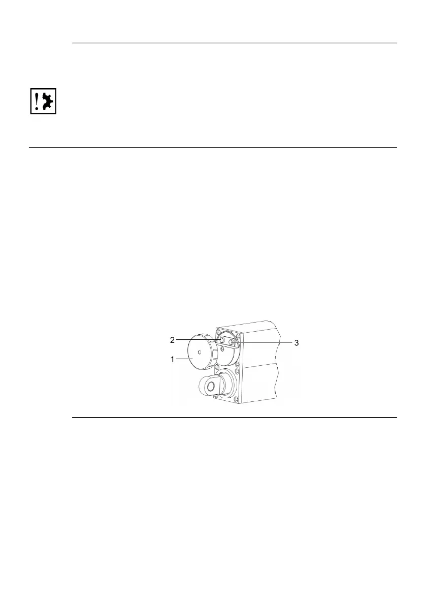
The setting buttons are located on the front of the housing beneath a cover.
Before programming or adjusting the limit positions, the cover must be removed
by turning around the circumference (anti-clockwise). Once programming is
complete, the cover must be replaced without delay.
Fig. 2 Setting button
1 Cover
2 Green button
3 Red button
The electronic limit switch has the function of monitoring the position of the
connecting rod and switching the corresponding relay contacts when the taught-
in positions are reached. These must be evaluated by your control unit and
must lead to the immediate switching-off of the motor. In the case of the optional
brake, it must be switched simultaneously (see section 4.3.1 "Optional brake").