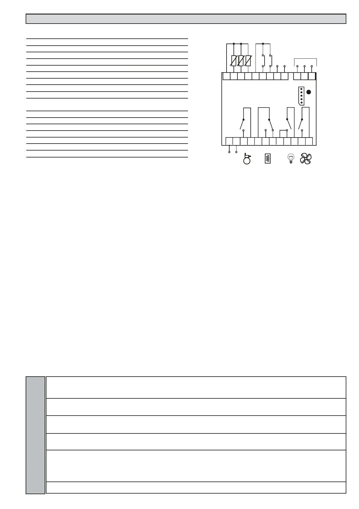
WIRING DIAGRAM EWDR 985/CSK (LX) - LINK
TERMINALS
1-2 Probe input 1 (room probe)
1-3 Probe input 2 (evaporator probe)
1-4 Probe input 3 (display or 2nd evaporator probe)
5-6 Digital input 1
5-7 Digital input 2
8-9 Link (8= +; 9= -)
10-12 RS485 network
13-14 Power supply 230Va
A TTL input for Copy Card
15-16* N.O. relay output (A) see par. H24 (compressor default)
17-18* N.O. relay output (B) see par. H22 (defrost default)
17-19* N.C. relay output (B) see par. H22 (defrost default)
20/21-22* N.O. relay output (C) see par. H21 (light default)
23-24* N.O. relay output (D) see par. H23 (fan default)
* Relay characteristics
Relay output (C) 15A 1hP 250Va
Relay output (A) (B) (D) 8(3)A 1/2hP 250Va
Link-label Lin
L00 Selects the instrument as Master
(0), Slave (from 1 to 7).
0...7 0 2 num
L01 Number of Slaves in the Network Refers to Master
only Number of Slaves in network (from 0 to 7).
For the Slaves leave value =0
0...7 0 2 num
L03 Refers to Master and Slave Defrosting
Simultaneous/sequential. Master: n = sequential;
y = simul taneous. Slave: y = accept; n = ignore.
n/y n 2 Flag
L04 Refers to Slave only. Distributed display.
n = Slave displays local values;
y = Slave displays Master display
n/y y 2 Flag
L05 Activation of Master network functions: n = does
not ask Slaves for activation of remote functions;
y =asks Slaves for activation of remote functions.
Slave: n = ignores activation of remote functions
from Master; y = accepts activation of remote
functions from Master.
n/y n 2 Flag
L06 Shuts down resources (compressors, fans, etc) at
end of defrosting. n=no; y=yes
n/y y 2 Flag
EWDR 983-985/CS (LX) - EWDR 985/CSK (LX) 12/12
H24 H22 H21 H23
LINK
The Link function is used to connect up to
8 instruments (1 Master device and 7 slave
devices). The distance between one device
and another must be 7 metres maximum
whereas the maximum distance between
the first and last instrument in the network
must be approximately 50m.
NOTE: the serial link between the devices is
powered.
Master
Instrument that controls the networks and
sends commands to the Slaves. The Master
is selected using parameter L00 (the value 0
defines the Master)
Slave
Instrument(s) with own controllers that also
perform(s) commands issued by the Master
(with parameters L03..L06).
Defrosting
The Link network controls defrosting. The
Master sends the defrost command which
can be performed synchronously (at the
same time) or sequentially (one defrost
after another) without affecting the normal
protections or delays for each instrument
(see parameter L03).
Other Functions
The Master can also activate the functions
associated with buttons or the Digital Input
for all the Slaves: switching lights on/off,
alarm silencing, auxiliary set point, auxiliary
relay, stand-by (on/off) and functions relat-
ed to Night & Day controller (see parame-
ter L05).
The Master can also synchronize the Slave
displays with the Master device display (see
parameter L04).
NOTE: synchronized defrosting refers to
actual defrosting and not to dripping and
subsequent defrosting. The defrost LED on
the Slave units blinks when synchronized
defrosting has terminated and the Slaves
are awaiting for the thermostat control to
be enabled by the Master.
The functions are associated with the
instruments by correctly setting the para-
meters (see the parameter table for the
“Lin” label folder)
LINK ALARM
In the event of a master/slave communica-
tion failure, the No Link alarm is signalled.
This alarm condition can be viewed on the
master and slaves, if present, in the “AL”
folder with the “E7” label.
NOTE:
•The E7 error is signalled after approx. 20
seconds in “no link” condition to avoid
any link disturbance causing communica-
tion errors.
•The E7 error is also signalled for address-
ing conflicts when:
a) the number of Slaves set on the MAS-
TER is different from the actual number of
Slaves on the network
b) 2 or more Slaves have the same
address.
•In the event of addressing errors, E7 will
not be shown, but the display will blink.
 Loading...