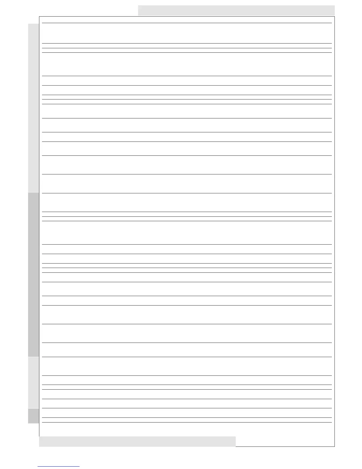
PAR.
HC1
OS1
db1
dF1
HS1
LS1
HA1
LA1
dn1
do1
di1
dE1
On1
OF1
HC2
OS2
db2
dF2
HS2
LS2
HA2
LA2
dn2
do2
di2
dE2
On2
OF2
dSi
dSt
Unt
SEn
Sdi
Con
CoF
7/10
DESCRIPTION
CONTROLLER 1 (folder with “rE1” label)
Regulating mode. If set to H, the controller operates in heating mode.
If set to C, the controller operates in cooling mode.
Offset Set point 1
Regulation band 1 See ON-OFF regulation diagram
Relay 1 intervention differential. The load will stop when Set point 1 is
reached (as indicated by the control probe) and will restart at a tem-
perature equal to Set point 1 plus (or minus depending on HC1) the
value of the differential. See ON-OFF reg. diagram
Maximum value for set point 1. By default, it will be set to the maxi-
mum value that the probe can reach.
Minimum value for set point 1. By default, it will be set to the mini-
mum value that the probe can reach.
Maximum alarm OUT 1 See Max/Min. Alarm diagram.
Minimum alarm OUT 1 See Max/Min. Alarm diagram.
CONTROLLER 1 PROTECTIONS (folder with “rE1” label)
Start-up delay. The specified time must elapse between the controller
relay start-up request and actual start-up.
Delay after shut-down. The specified time must elapse between shut-
down of controller relay and a subsequent start-up.
Delay between start-ups. The specified time must elapse between two
subsequent start-ups of the controller.
Shut-down delay. The specified time must elapse between the con-
troller relay shut-down request and actual shut-down.
NOTE: for parameters dn1, do1, di1, dE1 0= not active
Controller start-up time if probe is faulty. If set to “1” with Oft at “0”
the controller is always on whereas if Oft >0 it operates in duty cycle
mode.
See Duty Cycle diagram
Controller shut-down time if probe is faulty. If set to “1” with Oft at
“0” the controller is always off whereas if Oft
>0 it operates in duty cycle mode.
See Duty Cycle diagram
CONTROLLER 2 (folder with “rE2” label)
Regulating mode. If set to H, the controller operates in heating mode.
If set to C, the controller operates in cooling mode.
Offset Set point 2
Regulation band 2 See ON-OFF regulation diagram
Relay 2 intervention differential. The load will stop when the Set point
is reached (as indicated by the control probe) and will restart at a
temperature equal to Set point 2 plus (or minus depending on HC2)
the value of the differential. See ON-OFF reg. diagram
Maximum value for set point 2. By default, it will be set to the maxi-
mum value that the probe can reach.
Minimum value for set point 2. By default, it will be set to the mini-
mum value that the probe can reach.
Maximum alarm OUT 2 SEE ALARM DIAGRAM HIGH AND LOW T.
minimum alarm OUT 2 SEE ALARM DIAGRAM HIGH AND LOW T.
CONTROLLER 2 PROTECTIONS (folder with “rE2” label)
Delay in start-up of controller 2. See dn1
Delay after shut-down. The specified time must elapse between shut-
down of controller 2 relay and a subsequent start-up.
Delay between start-ups. The specified time must elapse between two
subsequent start-ups of controller 2.
Delay in shut-down of controller 2. The specified time must elapse
between the controller relay shut-down request and actual shut-down.
NOTE: for parameters dn2, do2, di2, dE2 0= not active
Controller start-up time if probe is faulty. If set to “1” with Oft at “0”
the controller is always on whereas if Oft >0 it operates in duty cycle
mode.
See Duty Cycle diagram
Controller shut-down time if probe is faulty. If set to “1” with Oft at
“0” the controller is always off whereas if Oft >0 it operates in duty
cycle mode. See Duty Cycle diagram
SOFT START (folder with “SFt” label)
dynamic Step increment (Step Value). Value (in degrees)of each of
subsequent increases (dynamic) of adjustment point. 0=disables SOFT
START function.
dynamic Step time (Step Duration). Time between two subsequent
increases (dynamic) of set point
Unit of measurement (hours, minutes, seconds)
Enabled outputs. Establishes which outputs the function must be
enabled on: 0 = disabled; 1 = OUT 1; 2 = OUT 2; 3 = OUT 1 & 2;
Function reinsertion threshold. Establishes the threshold beyond which
the SOFT START function is automatically re-inserted
PERIODIC CYCLE (folder with “cLc” label)
Output ON time.
Output OFF time.
Tab. 1 Table of parameters
DEFAULT*
C
0
1
1
140
-50
140
-50
1
0
0
0
0
1
C
0
1
1
140
-50
140
-50
1
0
0
0
0
1
0
0
1
1
0
0
0
RANGE
H/C
-30.0...30.0
0...30.0
0.0...30.0
LS1..HdL
LdL..HS1
LA1…350.0
-99.9…HA1
0...250
0...250
0...250
0...250
0...250
0...250
H/C
-30.0...30.0
0...30.0
0.0...30.0
LS2..HdL
LdL..HS2
LA2…350.0
-99.9…HA2
0...250
0...250
0...250
0...250
0...250
0...250
0…25.0
(0...twenty-five.0)
0…250
0/1/2
0/1/2/3
0…30.0
0…250
0…250
VALUE**
U.M.
flag
°C/°F
°C/°F
°C/°F
°C/°F
°C/°F
°C/°F
°C/°F
°C/°F
sec
min
min
sec
min
min
flag
°C/°F
°C/°F
°C/°F
°C/°F
°C/°F
°C/°F
sec
min
min
sec
min
min
°C/°F
H/m/sec
H/m/sec
num
°C/°F
min
min
LEVEL***
1
2
1
1
1
1
1
1
1
1
1
1
1
1
1
2
1
1
1
1
1
1
1
1
1
1
1
1
2
2
2
2
2
2
2
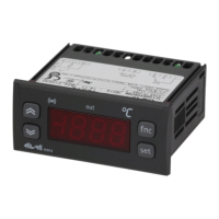
IC 915 LX
SP1: Control SetPoint 1, range LS1...HS1
SP2: Control SetPoint 2, range LS2...HS2
***NOTE: At level 1 the folders will only display all the level 1 parameters. At level 2 the folders will only
display all the level 2 parameters.
rE1
re2
SFt
CLc