DIFFERENTIAL ADJUSTMENT
DIFFERENTIAL ADJUSTMENT
For this type of adjustment, set:
•folder CnF, parameter H42=y indicating
the presence of probe Pb2;
•folder CnF, parameter H03=1 indicating
the type of adjustment (=1, adjustment
according to Pb1-Pb2 difference compared
with set point;
On the basis of these settings, the new
adjustment value is calculated according
to the difference between the values read
by the two probes “diff”=Pb1-Pb2.
If the difference is positive (Pb1> Pb2) or
negative (Pb2>Pb1) but lower or equal to
the value of the set point (SP1>”diff”, or
SP1=”diff”) the output set “for heating”
will be activated.
If the difference is positive (Pb1> Pb2) but
higher than the value of the set point
(SP1>”diff”) the output set “for cooling”
will be activated.
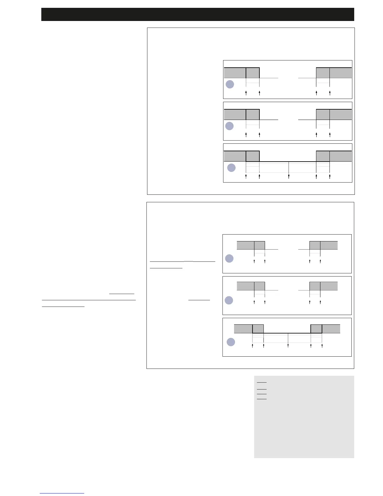
-->Adjustment varies according to parame-
ter H01 that determines the link between
the outputs. See diagram on right.
SETPOINT=OFFSET ADJUSTMENT
SETPOINT=OFFSET ADJUSTMENT
compared with Pb2.
compared with Pb2.
For this type of adjustment, set:
•folder CnF, parameter H42=y indicating
the presence of probe Pb2;
•folder CnF, parameter H03=2 indicating
the type of adjustment (H03=2, adjust-
ment of set point calculated as offset from
probe Pb2;
On the basis of these settings, the new
adjustment value “SE= effective set point”
is calculated according to the sum of the
set point offset (see parameter SP1) and
the value read by probe Pb2 within the
new setting limits defined by parame-
ters LLS and HLS.
The control input is always determined by
Pb1.
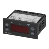
-->Adjustment varies according to parame-
ter H01 that determines the link between
the outputs. See diagram on right.
IC 915 LX 5/10
DIFFERENTIAL and SET POINT OFFSET ADJUSTMENT
HC1
H*
H*
-
H* maximum set point controller with differential
dF1 negative
C** minimum set point controller with differential
dF2 positive
NOTE:
•for 1 and 2 examples with HC1=H e HC2=C;
•for 3 HC1 and HC2 settings are ignored
HC2
C**
C**
-
H01
0
1
2
type of regulation
independent set points
dependent set points
Neutral Area (or window)