BUTTONS AND MENUS ACCESSING
AND USING MENUS
The resources are arranged in a menu that
can be accessed by pressing and quickly
releasing the “set” button (Machine Status
menu) or holding down the “set” button
for more than 5 seconds (Programming
menu).
To access the contents of each folder indi-
cated by the relevant label, just press the
“set” button once.
You can now scroll through the contents
of each folder, modify it or use its func-
tions. If you do not use the keyboard for
over 15 seconds (time-out) or if you press
the “fnc” button once, the last value
shown on the display is confirmed and you
are taken back to the previous screen
mask.
MACHINE STATUS MENU
(See Machine Status Menu Diagram)
To access the Machine Status menu, press
the “set” button and quickly release it.
The “SP1” label appears.
(If alarms are active, with the exception of
faulty probes/probe errors, the “AL” label
appears).
By using the “UP” and “DOWN” buttons
you can scroll through the other folders in
the menu: the folders are indicated below
in the order they appear:
-SP1: Set point 1 setting folder or
-AL: alarm folder (if alarms present, with
exception of faulty probes/probe errors);
-SP2: Set point 2 setting folder.
-Pb1: probe 1 value folder;
-Pb2: probe 2 value folder;
The folders are present according to
the presence and configuration of the
associated resource.
Alarm on
If an alarm condition exists when the
Machine Status menu is accessed, the “AL”
folder label appears (see “Diagnostics”
section).
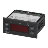
USER INTERFACE
The user has a display and four buttons
for controlling instrument status and pro-
gramming.
IC 915 (LX)
electronic controller with 2 set points and differential set point
adjustment
cod. 9IS23071
rel. 12/04
GB
Alarm
•ON for active
alarm;
•blinking when
a silenced alarm
is still present
out2
Relay 2 (OUT2)
ON for relay on
(energized);blin
king for protec-
tion delay or
enabling
blocked
out1
Relay 1 (OUT1)
ON for relay on
(energized);blin
king for protec-
tion delay or
enabling
blocked
Soft Start
ON when Set
point is being
set
(and Set point
setting)
blinking when
Soft Start func-
tion is on
Set-point/
Reduced set
point
•ON to modify
Set-Point;
•blinking when
reduced set
point is entered
MACHINE STATUS MENU DIAGRAM
LEDs
out2 out1
Scrolls through the menu items UP button
Increases the values
Parameter programmable
(par. H31)
DOWN button
Scrolls through the menu items
Decreases the values
Parameter programmable
(par. H32)
fnc button ESC function (quit)
Parameter programmable
(par. H33)
Set point button 1-Accesses Machine Status Menu
(SET POINTS, ACTIVE ALARMS,
PROBE READING) and labels/values;
1-Accesses Programming Menu
(PARAMETERS, COPY C ARD) and
relative labels/values;
3-Confirms commands