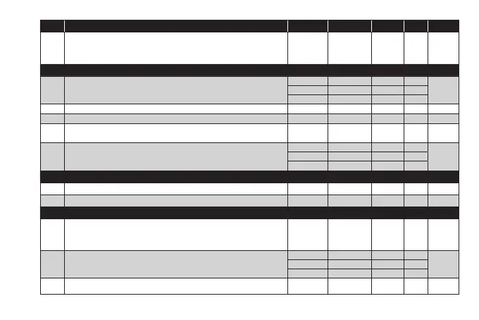
PAR. DESCRIPTION MODEL RANGE VALUE M.U. LEVEL
OF2
Controller 2 switch-off time in the event of faulty probe.
if OF2=1 and On2=0, the controller remains off;
if OF2=1 and On2>0, the controller operates in Duty Cycle mode.
ALL 0...250 1 min Inst
SOFT START CONTROLLER (folder ‘SFt’)
dSi
Value (in °C) of each subsequent increase (dynamic) of the setpoint.
0 = disabled.
NTC/PTC 0.0...25.0 0.0 °C/°F
InstPT100-Tc 0.0...25.0 0.0 °C/°F
V/I 0...25 0 num
dSt Time between two subsequent increases (dynamic) of the Setpoint. ALL 0...250 0 min Inst
Unt Unit of measurement (parameter dSt). 0 = hours; 1 = minutes; 2 = seconds. ALL 0/1/2 0 num Inst
Sen
Establishes which outputs the function must be enabled on:
0 = disabled; 1 = OUT 1; 2 = OUT 2; 3 = OUT 1 & 2
ALL 0/1/2/3 0 num Inst
Sdi
Function reactivation threshold. Establishes the threshold beyond which the
SOFT START function is automatically reactivated.
NTC/PTC 1.0...50.0 2,0 °C/°F
InstPT100-Tc 1.0...50.0 2.0 °C/°F
V/I 1...50 2 num
CYCLIC CONTROLLER (folder ‘cLc’)
Con Output ON time. ALL 0...250 0 min Inst
CoF Output OFF time. ALL 0...250 0 min Inst
ALARMs (folder ‘AL’)
Att
Parameters ‘HA1/HA2’ and ‘LA1/LA2’, intended as the absolute temperature
value or differential in relation to the setpoint.
AbS (0) = absolute value; rEL (1) = relative value.
ALL AbS/rEL AbS flag Inst
AFd Alarm differential.
NTC/PTC 1.0...50.0 2.0 °C/°F
InstPT100-Tc 1.0...50.0 2.0 °C/°F
V/I 1...50 2 num
PAO Alarm override time after device is switched on following a power failure. ALL 0...10 0 hours Inst