ES 50 – ES 80
19
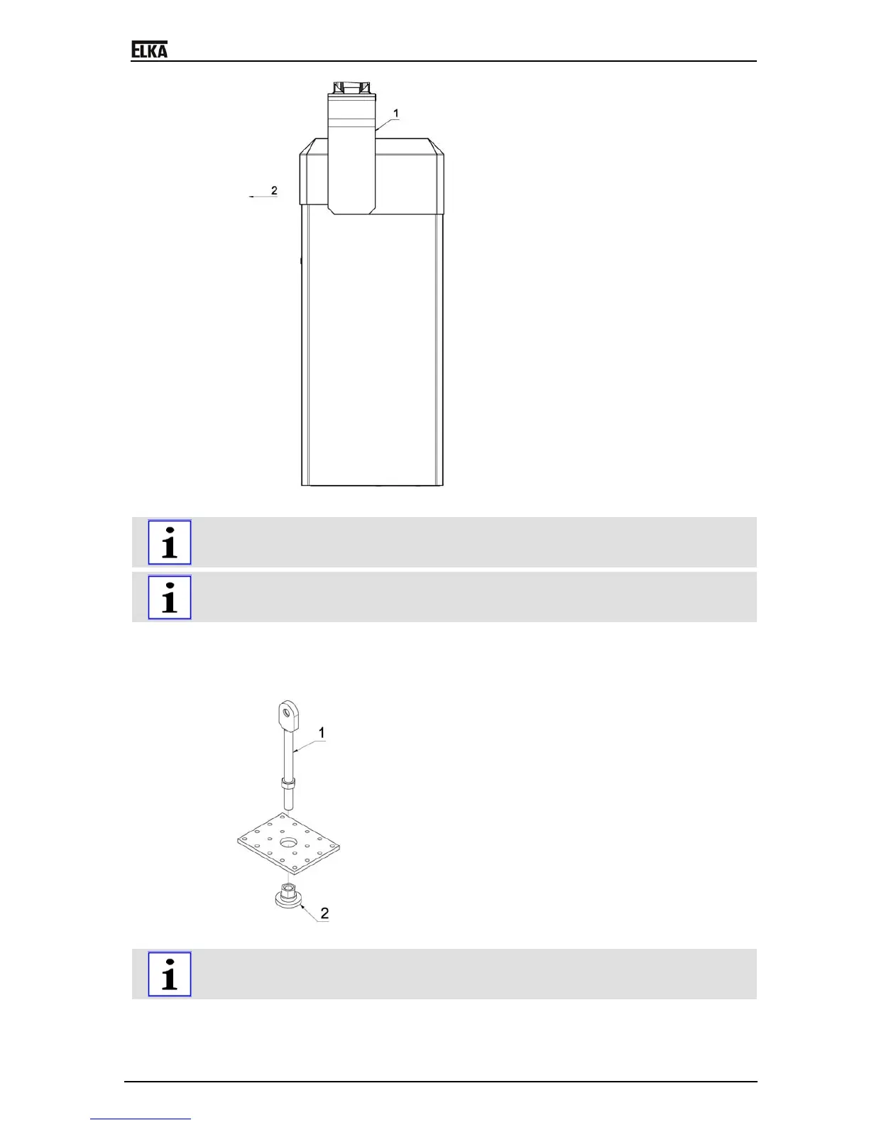
Drawing 5
The barrier is open when delivered, i.e. the boom connector wings have to be mounted vertically
upwards. During mounting the larger hub distance has to point in direction to the access panel (2).
Please also observe the stickers at the boom connector wings („OBEN-TOP-HAUT”).
The wings (1) for the boom connectors are different for the left and right side.
The wings are numbered (on the carton) in pairs and each pair is assigned for a certain barrier
mechanics.
4. Connect the wings for the boom connector to both ends of the main shaft. 4 of the 16 tapped holes
are numbered in handwriting and the inserted grub screws have to be tightened in the
corresponding order.
5. Secure the boom holder on the assembly. The two parts are then joined together.
Drawing 6
For the above drawing the tension springs were graphically removed. Do not loosen the tension
springs from the spring plate during installation / disassembly of the spring assembly.
6. Remove the adjusting nut from the spring assembly. If the boom is to be shortened reduce the
number of springs. The following table shows approximate values, check that the balance is as
described under f). The springs must be divided equally between the back and the front. One


 To Next Page