ES 50 – ES 80
18
8 Installation ES 50 – ES 80
Basic requirements
Keep a safety distance of min. 500mm between all moving barrier parts and surrounding objects
like walls, fences etc.
When preparing the foundation consider the alignment and distance related to a (optional) fixed
support.
The installation of barriers in flood areas is prohibited.
REMARK!
For the barrier foundation we recommend a concrete strength class of C20/25 (or higher) and the use
of chemical dowels (M12).
WARNING!
Risk of injury by insufficient fastening!
Tilting barrier housings can result in severe injuries.
Before installation ensure a safe stand oft he barrier housing.
Do not lean the barrier boom against a wall or similar before isntallation. Store the boom
horizontally only.
Install the barrier housing as specified.
Use the recommended heavy duty anchor bolts M12, at least M10 is required.
During maintenance check the housing for a correct fasenting on the foundation.
1. Before preparing the foundation lay enough underground cable (provide for a sufficient number of
wires) or a plastic cable conduit for a later cable installation. The foundation has to be absolutely
frost-free and with a horizontal surface of 600 x 650mm (if possible, at least 30mm higher than the
surrounding ground).
Drawing 4
2. Using the provided template you can either grout bolts (min. 12mm) into the foundation at the
appropriate positions or drill holes into the hardened concrete for heavy-duty fixings. Secure the
barrier on its foundation. For a correct functioning make sure the barrier housing is in a
perpendicular position.
nchor the spring assembly with all four fastening points through the housing into the foundation (see
drilling template ).
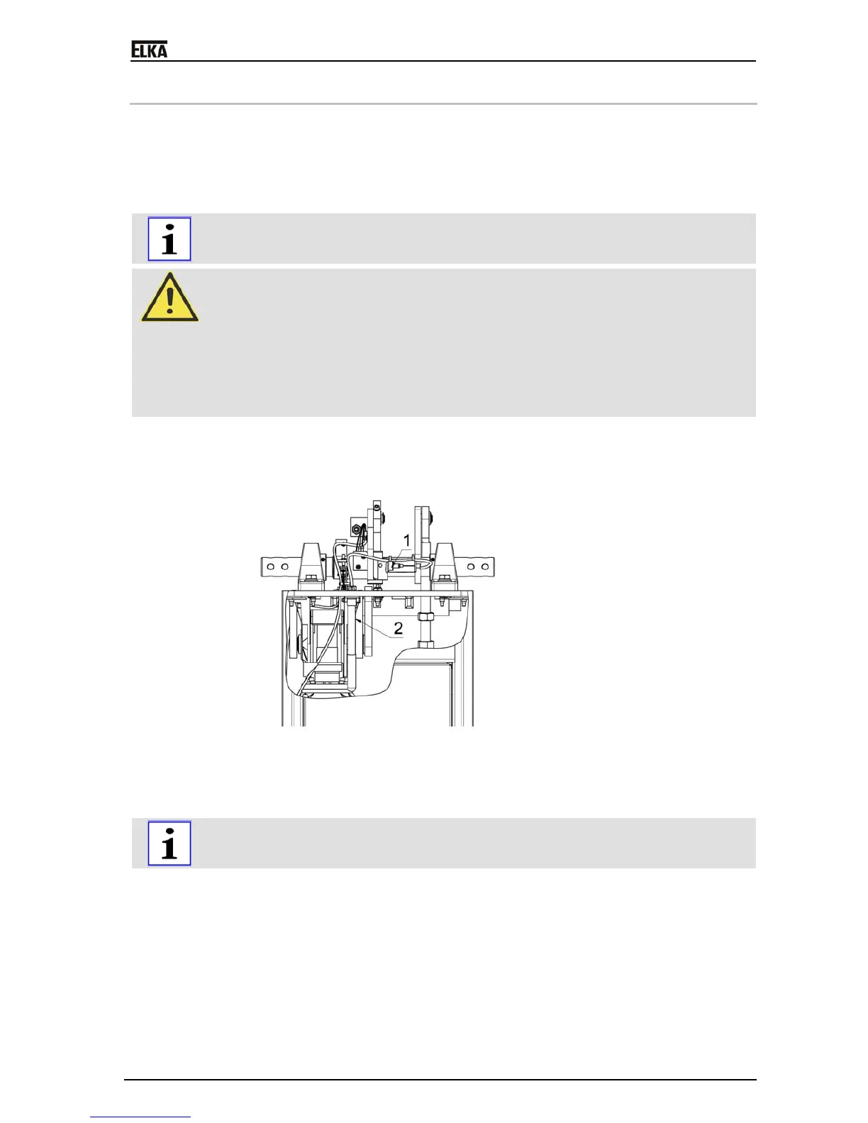
3. To open (release) the barrier boom during installation and current failure, pull the release lever
(2). The barrier can now be opened manually. In the vertical position the bolt (1) engages
automatically. To close (reposition) the barrier boom pull the lever again and move the boom
manually downwards.


 To Next Page