0000001028 (Rev. G - 11/18)
EDFP217WS EDFP217WS*F
Page 3
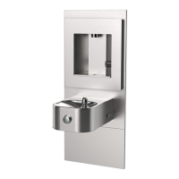
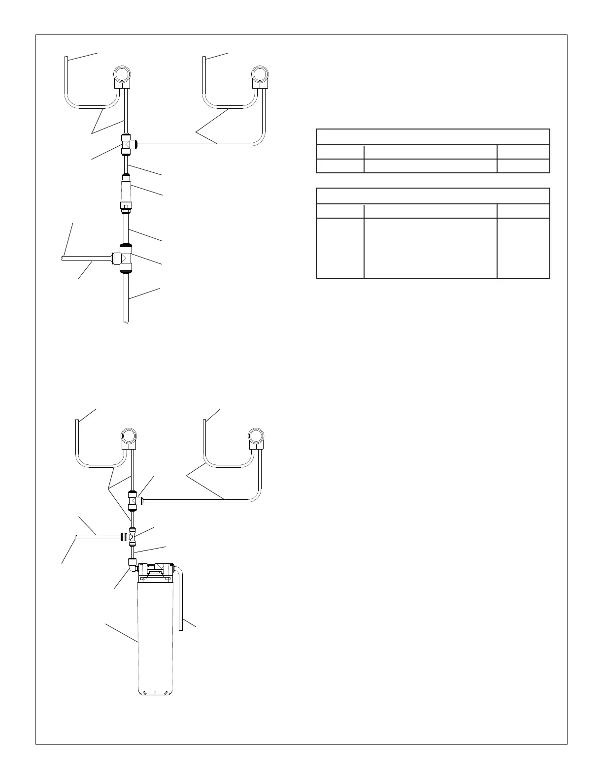
Figure 3 - LZWS-EDFP217K Tube Routing
REQUIRED TOOLS AND MATERIALS
These tables show special tools and/or additional materials
(not provided) which are necessary to complete installation
of these units:
10
10
23
TO BUBBLER
10
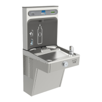
Figure 2 - EZWS-EDFP217K Tube Routing
TO BUBBLER
31
FILTER
ASSEMBLY
11
10
10
WATER
INLET
Special Tools
Item
Description
Quantity
NONE
Additional Materials Not Included
Item
Description
Quantity
Unplated copper inlet pipe
Service Stop
90° 1-1/4” Drain Line
1-1/4” Tee Drain Line
1
2
3
4
1
1
1
1
WATER
INLET
TO BUBBLER
24
TO BOTTLE
FILLER
TO BUBBLER
22
11
12
TO BOTTLE
FILLER
10
31
29
1. Make water supply connections (Fig. 10). Install a shut-o valve
and union connection to building water supply (valve and union
not provided). Turn on water supply and ush the line thoroughly.
Caution: DO NOT SOLDER tubes inserted into the
strainer or lter head as damage to the o-rings may result.
2. Install mounting frame (instructions supplied with mounting
frame.
3. (For LZWS-EDFP217K) Install the lter head to the bracket,
then install lter bracket on mounting frame (Fig. 8), plumb from
the lter outlet using the ¼” elbow, poly tubing and ¼ x ¼ x 3/8”
tee, install lter.
3a. (For EZWS-EDFP217K) Install 3/8” tee, copper tubing and
strainer per (Fig. 2).
4. Install supplied 4” poly tubing and armaex to the outlet of the
previously installed tee or strainer. Connect supplied ¼ x ¼ x ¼
tee to the 4” poly tubing. With the back panel standing close to
the frame, connect 3/8” poly tube to the bottle ller.
5. Hang main panel on mounting frame hanger. Make sure the
power cord, reset switch wire & poly tube do not get pinched
between the panel & mounting frame. Ensure the panel engages
at the top. Align fountain holes with mounting frame holes.
6. Remove protective coating from main panel.
7. Install reset switch for bottle ller (Fig. 5). Snap the switch into
position after locating wires through slot. Wrap up the excess
cord.
 Loading...