Installation 2
gas-net F1
Page 2-7
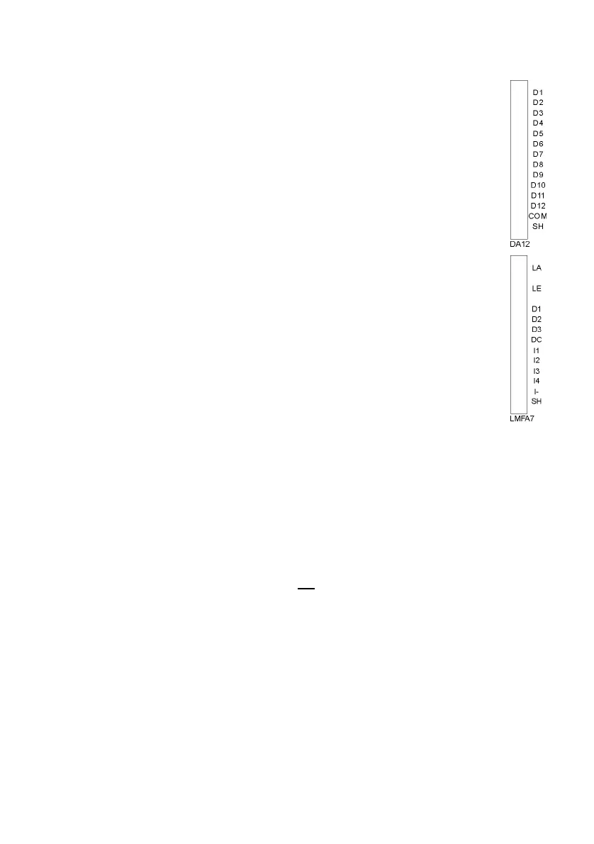
2.2.2.8 DA12 Output Board
The digital DA12 output board has 12 transistor outputs for the output of
messages or volume pulses (to be connected to terminals D1,…,D12
with the common reference point COM). Connect the cable shielding for
the outputs to the SH terminal.
2.2.2.9 LMFA7 Output Board
The LMFA7 output board offers 3 digital outputs: one relay output
(active break contact) for the output of a message and two transistor
outputs for the output of messages or pulses. Connect the outputs via
terminals D1, D2, D3 with the common ground DC.
Furthermore, the LMFA7 board is equipped with 4 analog outputs
0/4..20 mA (terminals I1, I2, I3, I4 with common ground I-).
The terminals named LA and LE right at the top of the board are
reserved for later expansions (LA = fiber-optics output, LE = fiber-optics
input).
Connect the cable shielding to the SH terminal of the board.
2.2.3 Further Connection Possibilities
2.2.3.1 Serial Interface DSS
The serial interface DSS in form of a SUB-DB 9 female connector on the front
panel serves the connection of the gas-net F1 to other devices, such as a laptop
computer or PC. The technical data is stated in the annex. An interconnecting
cable to the computer can be delivered as accessory. A standard COM
connection (one-to-one connection) is not
permissible.
2.2.3.2 DSfG Interface (optional)
The DSfG protocol is an internal protocol for gas meters for data transmission
between devices of the gas-net series.
The DSfG interface is a SUB-DB 9 male connector located on the back of the
device. Secure the connector with screws.
 Loading...