3 Installation of Flatpack2 Modules
20 User’s Guide Flatpack2 Rectifier & Converter Modules, 350002.013, 8v1-2013-08
Connections
All connections are implemented by inserting the Flatpack2 module fully into the power
shelf, thus plugging the module to the self’s back wiring card (hot-pluggable).
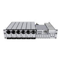
Figure 7 Flatpack2 module’s rear plug-in connections to power shelf’s back wiring card
For details about other power shelf signals, type of power shelf, etc., please read the
system’s generic and specific documentation, or contact your dealer or Eltek
representative.
Notice:
The AC Input Connections are not polarity sensitive, even when the system uses DC input feed instead of AC input feed.
CAN Bus Addressing (plug-and-play)
When a Flatpack2 module is hot-plugged in the power shelf the first time, the system’s
main controller automatically assigns the module with the next available ID number (CAN
bus address). The module will retain its ID (and serial number), even after removing and
reinserting it in the power shelf.
The modules’ IDs are assigned from 1 and upwards. When a module is plugged in, the
system’s main controller automatically increases the number of communicating modules
in the CAN network.
Correct Rectifier Position in Power Shelves
Flatpack2 DC power systems are usually shipped from factory with the rectifier modules
already installed in the correct position in the power shelves, with respect to their CAN
bus address or ID number.
This relationship is very important for the correct monitoring of the mains three phases,
as the system’s main controller always uses rectifier ID 01, 02 and 03 to monitor mains
phase L1, L2 and L3 respectively. If these rectifiers malfunction, rectifier ID 04, 05 and
06 will automatically take over.
For example: accidentally inserting a rectifier with ID 02 in a power shelf position
internally connected to mains phase L1, will cause the controller to monitor L1 “thinking“
it monitors L2.
Flatpack2 rectifier
(rear plug-in slot)
DC Output
Power shelf (-)
DC Output
Power shelf (+)
AC input
connection
Module (L1)
AC input
connection
Module (L2)
Bus connection
Module (CAN-H)
Bus connection
Module (CAN-L)