4 Operation
22 User’s Guide Flatpack2 Rectifier & Converter Modules, 350002.013, 8v1-2013-08
4. Operation
The Flatpack2 Rectifier Module is designed for parallel operation in a system. The front
panel LEDs provides information about the module status and CAN bus activity.
Front Panel Interface
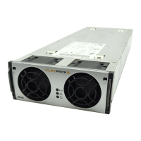
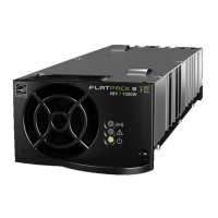
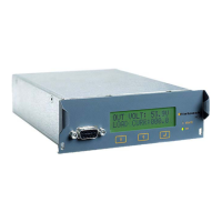
Figure 8 Example of a Flatpack2 module’s
front panel
The Flatpack2 module has the following LED indications:
“Power” (green) indicates that the power supply is OFF, ON and communicating
“Alarm” (red) indicates an alarm situation
“Warning” (yellow) indicates an abnormal situation
LED Indicators
The following events will activate the Flatpack2 module’s front LEDs:
System controller accessing information on the module
Module is in Derating Mode (reduced output power) due to
high internal temperature, or
low input voltage, or
fan failure
The remote Battery Current Limit is activated
AC input voltage is out of range
Module in stand-alone mode (or loss of communication with
the system’s main controller
Module is in Over-voltage Protection Mode (AC input)
No abnormal situation is present
Module is in Shut-down Mode due to
low mains, or
high internal temperature, or
high output voltage
Internal module failure (malfunction)
Fan failure (single or double fan malfunction)
Low output voltage
CAN bus failure
No alarm situation is present
Refer also to chapter “Technical Specifications”, page 23.
Warning
LED Lamp (yellow)