Do you have a question about the Eltek Flatpack MCU and is the answer not in the manual?
Details the Flatpack MCU's support for communication protocols and its advanced features for monitoring and control.
Lists standard alarm trigger events and their corresponding voltage ranges, and other alarm types.
Outlines the supported communication protocols, including pComm and COMLI.
Describes WinPower Silver as the primary PC interface for monitoring and control, with access levels.
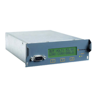
Describes the physical components of the Flatpack MCU front panel, including display, LEDs, and keys.
Explains the operation of the control keys on the front panel for navigating menus and selecting options.
Differentiates between user-accessible and password-protected service options for system configuration.
Guides the user through the installation process for the WinPower Silver communication software.
Details setup procedures for connecting the rectifier system to a PC, locally via RS232C or remotely via modem.
Explains how to establish a communication link and log into the WinPower Silver application.
Describes the functionality of the Site Manager for configuring and connecting to different system sites.
Provides an overview of the WinPower Silver software interface elements and their functions.
Outlines the two access levels (User, Service) and their respective rights within the WinPower Silver Main Menu.
Covers additional menu options not found in the main menu, such as Log Values and Symmetry Monitor.
Explains how to access and interpret the Alarm Status screen, including color indicators for alarm states.
Details various general configuration settings, including alarm limits, system time, and modem settings.
Covers the configuration of battery parameters, including setup, testing, boost charging, and limits.
Describes how to configure system-specific parameters like voltage, rectifier type, and LVD settings.
Explains the password protection system for accessing different levels of the MCU's menu options.
Details how to view, manage, and export the alarm log entries, which record system events and configuration changes.
Shows results from recent battery tests and indicates when the next test is scheduled.
Explains how to clear the event log from the main interface screen.
Describes the process of resynchronizing communication, often needed after changing installation settings.
Displays the default, minimum, maximum, and user-adjustable range for Battery Voltage.
Shows the default, minimum, maximum, and user-adjustable range for Boost Voltage.
Displays the default, minimum, maximum, and user-adjustable range for High Battery Alarm 1.
Displays the default, minimum, maximum, and user-adjustable range for High Battery Alarm 2.
Displays the default, minimum, maximum, and user-adjustable range for Low Battery Alarm 1.
Displays the default, minimum, maximum, and user-adjustable range for Low Battery Alarm 2.
Shows the default, minimum, maximum, and user-adjustable range for LVD1 Disconnect Point voltage.
Displays the default, minimum, maximum, and user-adjustable range for LVD1 Reconnect Point voltage.
Shows the default, minimum, maximum, and user-adjustable range for LVD1 Disconnect Delay time.
Displays the default, minimum, maximum, and user-adjustable range for LVD2 Disconnect Point voltage.
Shows the default, minimum, maximum, and user-adjustable range for LVD2 Reconnect Point voltage.
Displays the default, minimum, maximum, and user-adjustable range for LVD2 Disconnect Delay time.
Shows the default, minimum, maximum, and user-adjustable range for LVD3 Disconnect Point voltage.
Displays the default, minimum, maximum, and user-adjustable range for LVD3 Reconnect Point voltage.
Shows the default, minimum, maximum, and user-adjustable range for LVD3 Disconnect Delay time.
Displays the default, minimum, maximum, and user-adjustable range for Alarm Delay time.
Shows the default, minimum, maximum, and user-adjustable range for Low Temperature alarm threshold.
Displays the default, minimum, maximum, and user-adjustable range for High Temperature 1 alarm threshold.
Shows the default, minimum, maximum, and user-adjustable range for High Temperature 2 alarm threshold.
Displays the default, minimum, maximum, and user-adjustable range for Capacity Alarm percentage.
| Type | Control Unit |
|---|---|
| Application | Industrial |
| Communication Interface | CAN |
| Operating Voltage | 85-300 VAC, 120-400 VDC |
| Protection Features | Overvoltage, Overcurrent, Short Circuit, Over Temperature |
| Operating Temperature | -40°C to +70°C (consult datasheet) |