3 Local Operation of the Flatpack MCU
10
Operation Guide Flatpack MCU,
351300.013, v8-2006-07
3 Local Operation of the Flatpack MCU
3.1 The Front Panel
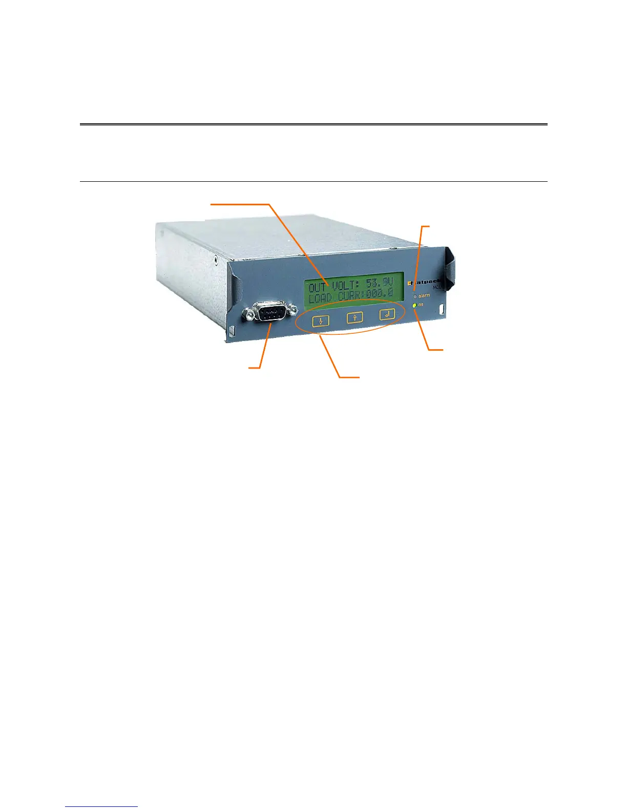
The Flatpack MCU control panel consists of a three-button keypad, a graphic display, a 9-pin D-Sub female
plug, a green LED (indicating that the system is ON) and a red LED (indicating that the system is in the
alarm mode).
The rectifier system is controlled from the Flatpack MCU by means of display menus and sub-menus.
The keypad on the front panel of the alarm module enables easy operation and retrieval of information.
This chapter describes the menus accessed from the front panel of the Flatpack MCU.
Additional menus and service-related information are accessed by connecting a PC to the front panel of the Monitoring
& Control Unit. Please Refer to chapter 4 Operating From a Personal Computer
Graphic display for local
system monitoring and
operation
Green LED
ON/OFF indication
Keypads for local
system operation
9-pin D-Sub female plug for remote
control from a PC o