4 Operating From a Personal Computer
Operation Guide Flatpack MCU,
351300.013, v8-2006-07
27
4.5 Description of the Screen Interface
After establishing the communication link between your PC and the rectifier system, the Flatpack MCU microprocessor
will take control of the PC screen. Operation of the rectifier system from a PC is based on pre-programmed menus
accessed from the main menu. The main menu and each function key are described in detail in the chapter 4.6 Main
Menu
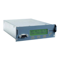
The screen interface includes the following information:
• System Info:
Customer: customer's name
Location: customer's location
Sw ver: software part no. and version no.
Unit's Date: current date yyyy/mm/dd
Unit's Time: digital clock
Access Level: USER or SERVICE
• Alarm Unit Status shows the system status, in ampere and volts, for the rectifier, batteries and load.
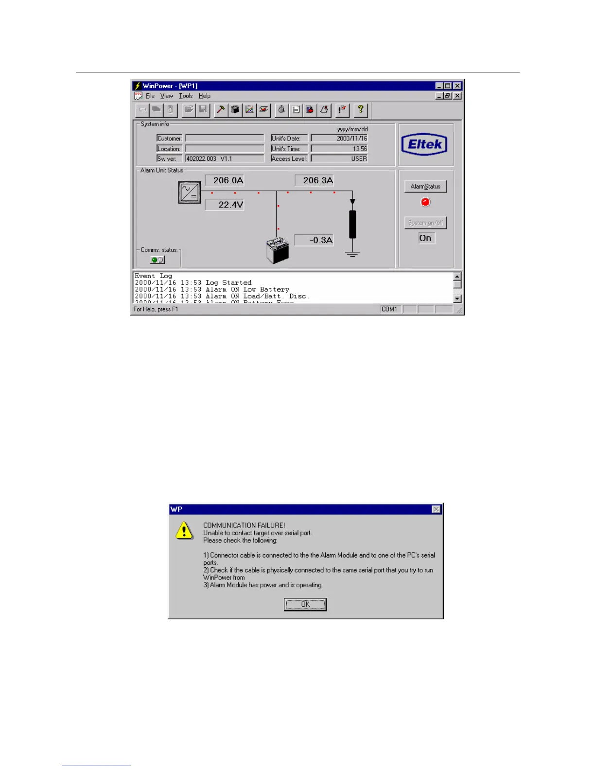
• Comms. status displays green alternating lights when the system is functioning without fault. The lights will stop
flashing when the system malfunctions and the following message will be displayed:
• AlarmStatus shows a red light when an alarm is active. A green light will show when all alarms are inactive.
• System On/Off displays the ON/OFF-status of the system. Access to System On/Off is only possible when in
SERVICE mode and may be disabled in some software versions.
• Event Log - System events are displayed in chronological order. The date, time and a description of each event is
shown. Note that the Event Log is for informational purposes only; while the Alarm Log is provided for alarm
recording.
• COM1, at the bottom of the screen, indicates the selected communication port.