4 Operating From a Personal Computer
32
Operation Guide Flatpack MCU,
351300.013, v8-2006-07
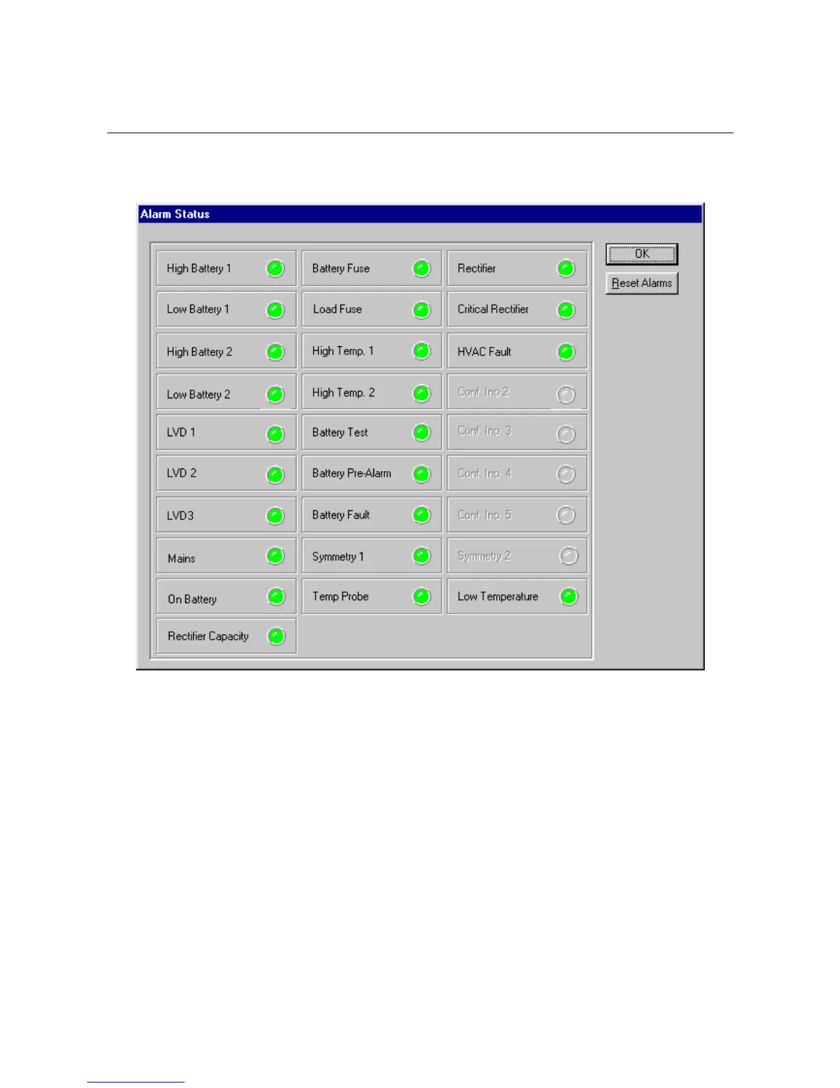
4.8 Alarm Status Screen
Clicking the Alarm Status button (above the colored indicator on the main screen) will open a window that displays a
summary of alarms and their current states. Colored indicators are used to denote alarm states: GREEN for Normal
(non-alarm state) and RED for Fault (alarm state). See image below.
Available options are:
OK – Close the Alarm Status window
Reset Alarms – Cycles and resynchronizes the alarm relay states. Active alarm relays are forced to non-alarm condition.
If the alarm still exists, these relays will again enter alarm condition after a short delay. Only “manual reset” alarms are
reset when performing an alarm reset.
4.8.1 Alarms Requiring Manual Resetting
These alarms require manual reset in order to preserve the alarm notification, if the alarm state subsequently clears. For
example, a Battery Symmetry alarm is triggered when the battery midpoint voltage exceeds a predetermined set point. It
is possible that the battery has experienced a momentary internal fault, which has caused this alarm to be reported. In
order to notify the site management personnel that this momentary event has occurred, the alarm is latched and requires
manual intervention to reset. Note that all alarm events, whether automatically or manually reset, are reported to the
Flatpack MCU alarm history log.
• Battery Pre-Alarm
• Battery Fault
• Symmetry 1