4 Operating From a Personal Computer
Operation Guide Flatpack MCU,
351300.013, v8-2006-07
23
4.2.4 RS-232 Cable pinouts – Remote Connection
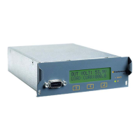
4.2.4.1 Cable from Flatpack MCU to Modem
The serial cable connecting the MCU to the modem may be either a 9 pin connection or 25 pin connection
at the modem depending on the modem type.
The serial cable in the drawing below is connected to the 9-pin D-sub male plug on Flatpack MCU and to
the 25-pin D-sub male plug on the modem’s port.
RS232C serial cable with 25- pin D – sub plug on the modem side.
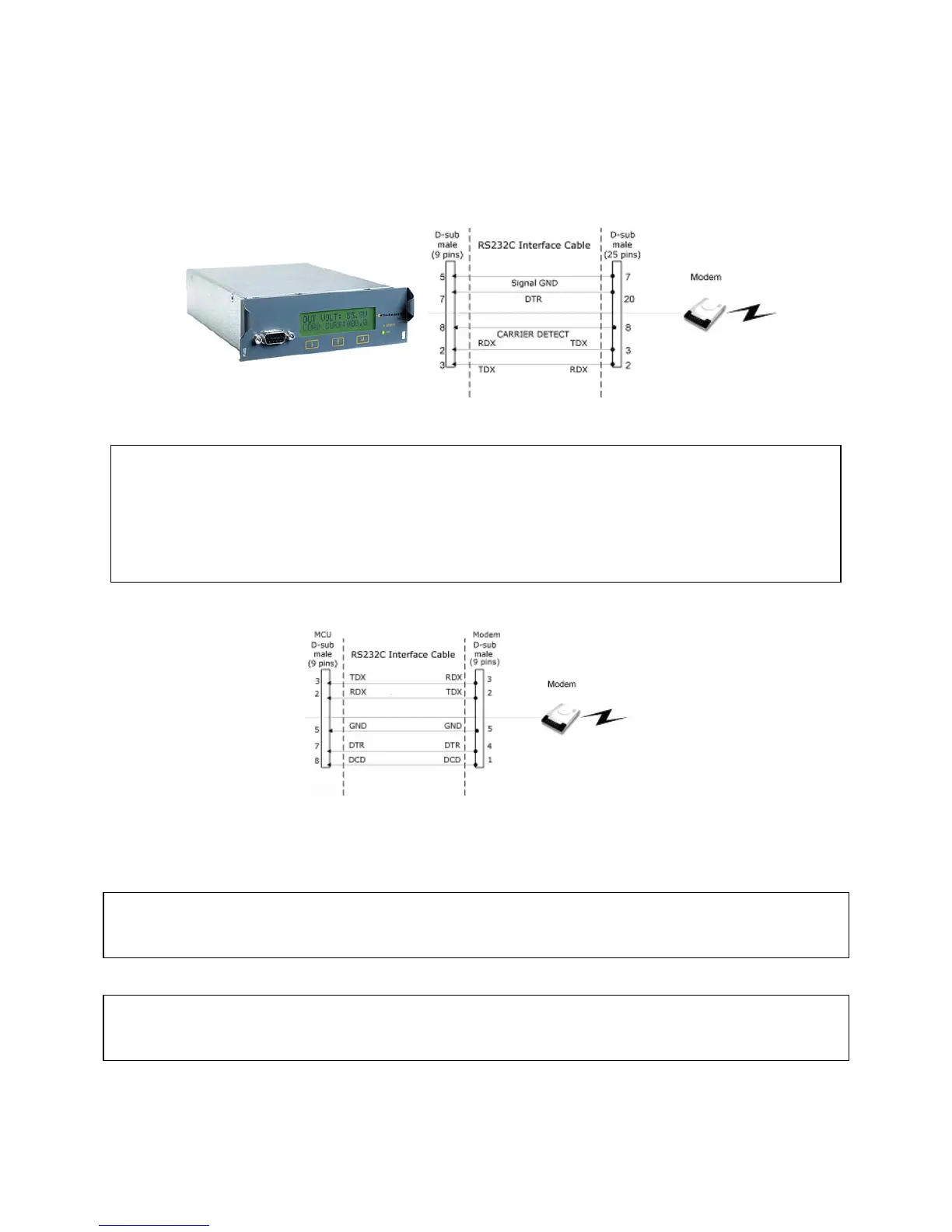
Where the modem has 9-pin connection the following drawing applies.
4.2.4.2 Cable from modem to PC
A standard RS232C serial cable is used when connecting a PC to a modem. The cable should have a 25-pin
D-sub male plug on the modem side, and a 9 or 25 pins D-sub female plug on the side of the PC.
9
A standard type RS232C serial cable can be supplied by Eltek Energy
9
Earth faults on the communication equipment must be rectified prior to connection
9
Note: the “TDX” signal (pin 3) from the alarm module is connected to the “RDX” signal (pin 2)
on the PC or modem
9
The RS232C serial cable can be supplied by Eltek Energy (6x0.22 mm
2
, length 200 cm, part.
no. 30615 for 25 pin modem)
«Earth» is connected to the cabinet’s chassis