4 Operating From a Personal Computer
Operation Guide Flatpack MCU,
351300.013, v8-2006-07
35
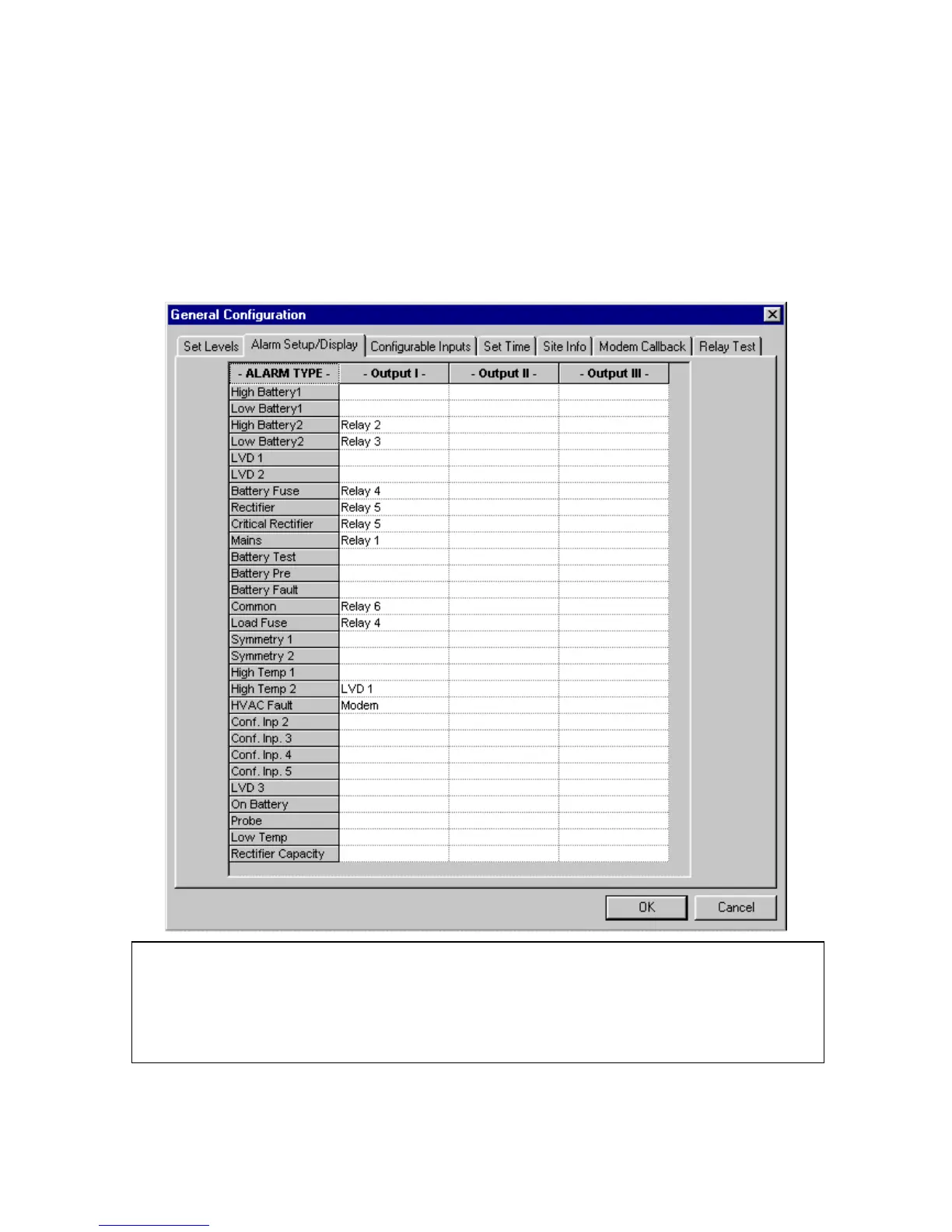
4.9.2 Alarm Setup/Display
This menu option illustrates, by means of a table, how the alarm relays are configured. Each system alarm or event may
activate one, two or three relay outputs, an LVD, or affect the modem callback. Several alarms may also activate the
same relay output, LVD, or be assigned to modem callback.
The current alarm relay configuration of your system will be displayed. All alarms in the system are, as default,
automatically reset when the cause of the alarm is removed. The alarm module enables resetting of all active alarms,
any alarms still active after resetting will again be reported.
To reset fault alarms from the PC:
• Select Alarm Status on the screen interface
• Reset the alarms from the Alarm Status displayed
9
NOTE: In the above screen capture, Configurable Input 1 has been renamed
“HVAC Fault” and is assigned to a modem. Also, High Temperature 2 is mapped to
LVD1 and will disconnect this LVD contactor when the temperature limit is
reached.