Serial Interface
Cable Wiring
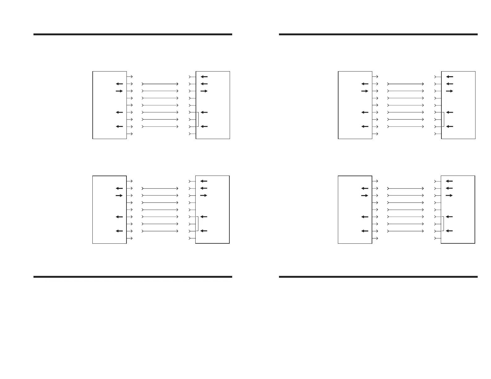
The figure below displays the cable wiring re-
quired to use the printer’s serial interface.
Serial Port
Mode Settings
The communication port mode setting should
be: 9600 baud, no parity, 8 data bits, and one
stop bit. An example of DOS Mode Statement
is shown below.
MODE COM2:96,N,8,1
N/C
RxD
TxD
DTR
GND
DSR
RTS
RI
CTS
PrinterHost
11
22
33
44
55
66
77
88
99
DB-9
Pin #
DB-9
Pin #
Female DB-9 to Male DB-9
Cable P/N 300017-006 (6') or 300017-010 (10')
N/C
RxD
TxD
DTR
GND
DSR
RTS
RI
CTS
PrinterHost
18
23
32
420
57
66
74
85
922
DB-25
Pin #
DB-9
Pin #
Female DB-25 to Male DB-9
Cable P/N 300018-006 (6')
*+5 volts at 150 mA for external device (e.g. KDU or scanner)
+5 Volts*
TxD
RxD
N/C
GND
RDY
N/C
N/C
RDY
+5 Volts*
TxD
RxD
N/C
GND
RDY
N/C
N/C
RDY
Troubleshooting
980090-001 Rev. B 41
Serial Interface
Cable Wiring
The figure below displays the cable wiring re-
quired to use the printer’s serial interface.
Serial Port
Mode Settings
The communication port mode setting should
be: 9600 baud, no parity, 8 data bits, and one
stop bit. An example of DOS Mode Statement
is shown below.
MODE COM2:96,N,8,1
N/C
RxD
TxD
DTR
GND
DSR
RTS
RI
CTS
PrinterHost
11
22
33
44
55
66
77
88
99
DB-9
Pin #
DB-9
Pin #
Female DB-9 to Male DB-9
Cable P/N 300017-006 (6') or 300017-010 (10')
N/C
RxD
TxD
DTR
GND
DSR
RTS
RI
CTS
PrinterHost
18
23
32
420
57
66
74
85
922
DB-25
Pin #
DB-9
Pin #
Female DB-25 to Male DB-9
Cable P/N 300018-006 (6')
*+5 volts at 150 mA for external device (e.g. KDU or scanner)
+5 Volts*
TxD
RxD
N/C
GND
RDY
N/C
N/C
RDY
+5 Volts*
TxD
RxD
N/C
GND
RDY
N/C
N/C
RDY
Troubleshooting
980090-001 Rev. B 41