Operation
Page 39
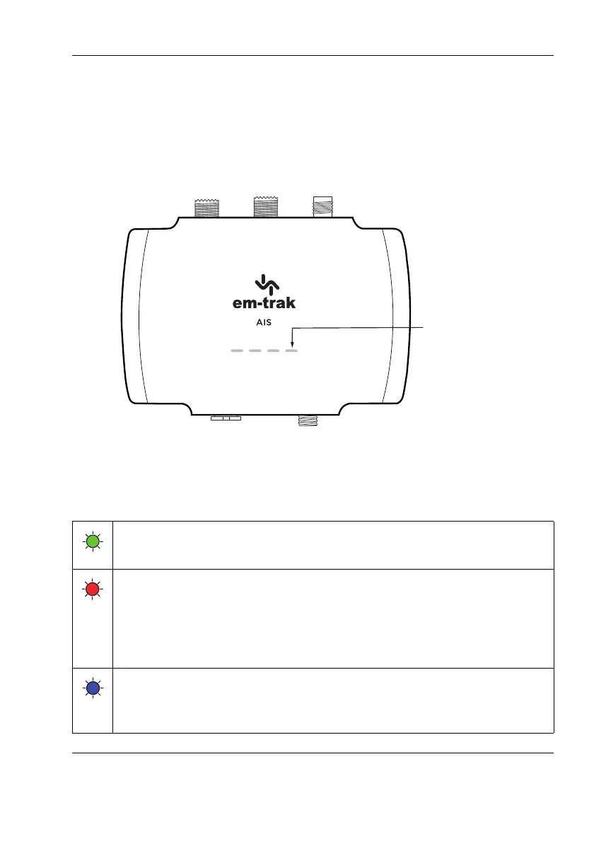
5.3 Indicator functions
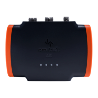
The AIS transceiver includes four coloured indicators as shown in Figure 16.
The state of the indicators provide information regarding the status of the AIS
transceiver.
Figure 16 Indicator location on the AIS transceiver unit
The meaning of each indicator is shown in the table below Figure 16 shows
the indicator positions on the AIS transceiver.
Green indicator
The AIS transceiver is configured and powered up.
Red indicator
The AIS transceiver has detected a system error. The likely causes
of this are detailed in the troubleshooting guide in
Section 8. Alarms
displayed in the Diagnostic tab of proAIS2 will also assist with
troubleshooting.
Blue indicator
When silent mode is activated using the optional silent mode switch
the transmitter is disabled.
 Loading...