EasyManua.ls Logo

Emakefun RF-NANO User Manual

Emakefun RF-NANO
34 pages
To Next Page IconTo Next Page
To Previous Page IconTo Previous Page
Page #7 background imageLoading...
Page #7 background image
Copy right © 2018 Shenzhen Emakefun Technology co., Ltd.
7
EEPROM :1KB ATmega328
CH340 USB to serial port chip
Clock 16 MHz
1.2.1 Power Supply
Arduino Nano power supply mode: mini-B USB interface power supply and external vin connection
7~12V external DC power supply
1.2.2 Memory
ATmega328 includes on-chip 32KB Flash, of which 2KB is used for Bootloader. There are also 2KB
SRAM and 1KB EEPROM.
1.2.3 Input and Output
14 digital input and output ports: The working voltage is 5V, and each channel can output and access
the maximum current of 40mA. Each channel is equipped with a 20-50K ohm internal pull-up resistance
(not connected by default). In addition, some pins have specific functions.
Serial signal RX (0), TX (1): It provides serial port receiving signal with TTL voltage level, connected
to the corresponding pin of FT232Rl.
External Interrupt (No. 2 and No. 3): Trigger interrupt pin, which can be set to rising edge, falling edge
or simultaneous trigger.
Pulse Width Modulation PWM (3, 5, 6, 9, 10, 11): Provides 6 channel, 8-bit PWM outputs.
SPI10(SS)11(MOSI)12(MISO)13(SCK):SPI Communication Interface.
LED (No. 13): Arduino is specially used to test the reserved interface of the LED. When the output is
high, the LED is lit. When the output is low, the LED is off.
6 analog inputs A0 to A5: Each channel has a resolution of 10 bits (that is, the input has 1024 different
values), the default input signal range is 0 to 5V, and the input upper limit can be adjusted by AREF. In
addition, some pins have specific functions.
TWI interface (SDA A4 and SCL A5): Supports communication interface (compatible with I2C bus).
AREF: The reference voltage of the analog input signal.
ResetThe microcontroller chip is reset when the signal is low.
1.2.4 Communication Interface
Serial port: The built-in UART of ATmega328 can communicate with external serial port through digital
port 0 (RX) and 1 (TX).
Question and Answer IconNeed help?

Do you have a question about the Emakefun RF-NANO and is the answer not in the manual?

Emakefun RF-NANO Specifications

General IconGeneral
MicrocontrollerATmega328P
Wireless ModulenRF24L01+
Operating Voltage5V
Input Voltage (recommended)7-12V
Input Voltage (limits)6-20V
Digital I/O Pins14
PWM Channels6
Analog Input Pins8
DC Current per I/O Pin20 mA
Flash Memory32 KB
SRAM2 KB
EEPROM1 KB
Clock Speed16 MHz
RF Frequency2.4 GHz
RF Output Power0 dBm
RF Sensitivity-85 dBm
RF Data Rate2 Mbps
Dimensions45mm x 18mm

Summary

Chapter 1 RF-NANO Introduction

1.1 RF-NANO Overview

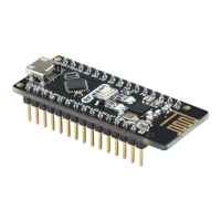
The board integrates an NRF24L01+ chip, combining NANO and NRF24L01+ for convenience.

1.2 RF-NANO MCU Introduction

Details the ATmega328 MCU, its features, voltage, memory, and I/O capabilities.

1.2.5 ATmega328 with NRF24L01+ Communication

Explains SPI communication between ATmega328 and NRF24L01+ with pin connections.

1.3 RF-NANO Driver Installation

Guides on installing the necessary drivers and IDE for the RF-NANO board, covering IDE and driver setup.

Chapter 2 RF-NANO Working Principle

2.1 RF-NANO Working Principle Introduction

Explains RF-NANO data transmission and reception, including modes and signal sequences.

2.2 RF-NANO Config Word

Details the SPI port communication and common configuration registers for the NRF24L01+ chip.

2.3 RF-NANO Working Modes

Describes the NRF24L01+ state machine and its five operational modes.

Chapter 3 RF-NANO Communication

3.1 Implement Two RF-NANO Point-to-Point Communication

Guides on establishing point-to-point wireless communication between two RF-NANO modules.

3.1.3 Point-to-Point Program Code

Provides transmitter and receiver C++ code for point-to-point communication.

3.2 Multiple Send to One Receive Communication

Details setting up multiple RF-NANO devices to send data to a single receiver.

3.3 One Send to Multiple Receive Communication

Explains setting up one RF-NANO to transmit data to multiple receiving devices.

Chapter 4 Transmitting Power and Data Rate

4.1 Set the Transmitted Power of RF-NANO

Explains software control of RF-NANO output power levels (-18dBm to 0dBm).

4.2 Set RF-NANO Data Transfer Rate

Details setting data transmission rates: 1Mbps, 2Mbps, or 250Kbps via software.