Copy right © 2018 Shenzhen Emakefun Technology co., Ltd.
WindowsXP System driver installation steps
If your computer is WindowsXP: the installation steps are basically the same as for Windows7, please
refer to the above Windows7 installation steps.
Chapter 2 working principle of rf-nano
2.1 working principle introduction of rf-nano
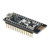
The rf-nano can transmit and receive data.
When transmitting data: first set NRF24L01+ as transmission mode: then put the receiving node address
TX_ADDR and effective data TX_PLD into NRF24L01+ cache by SPI port according to the time sequence.
If the automatic reply is turned on, NRF24L01+ will enter the receiving mode immediately after transmitting
data and receive the answering signal (the receiving address of the automatic reply should be the same as the
receiving node address TX_ADDR).If receive reply, consider the communication success, TX_DS set high, at
the same time TX_PLD from TX FIFO clear;If no reply is received, the data will be automatically
retransmitted (automatic retransmission is enabled). If the number of times of retransmission (ARC) reaches
the upper limit, MAX_RT will be set to a higher level, and the data in TX FIFO will be retained for subsequent
retransmission.When MAX_RT or TX_DS are set high, the IRQ becomes low and interrupts, notifies
MCU.When the launch is successful, if the CE is low, NRF24L01+ enters idle mode 1.If there is data in the
send stack and CE is high, it will enter the next launch.If no data is sent on the stack and the CE is high, then
idle mode 2 is entered.
When receiving data: NRF24L01+ is configured to receive mode first, followed by a delay of 130 microns
before it enters the receiving state and waits for the data to arrive.When the receiver detects a valid address and
CRC, the packet will be stored in RX FIFO. At the same time, the interrupt flag bit RX_DR is set to high, IRQ
becomes low, generating an interrupt, and MCU is informed to fetch the data.If the automatic reply is on at this
time, the receiver will enter the transmitting state to return the reply signal at the same time.When receiving
successfully, if CE decreases, NRF24L01+ enters idle mode 1.Always go into standby or power down mode
before writing registers.As shown in figure 2-1-1, SPI operation sequence diagram is given:

 Loading...