Do you have a question about the Emakefun RF-NANO and is the answer not in the manual?
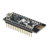
The board integrates an NRF24L01+ chip, combining NANO and NRF24L01+ for convenience.
Details the ATmega328 MCU, its features, voltage, memory, and I/O capabilities.
Explains SPI communication between ATmega328 and NRF24L01+ with pin connections.
Guides on installing the necessary drivers and IDE for the RF-NANO board, covering IDE and driver setup.
Explains RF-NANO data transmission and reception, including modes and signal sequences.
Details the SPI port communication and common configuration registers for the NRF24L01+ chip.
Describes the NRF24L01+ state machine and its five operational modes.
Guides on establishing point-to-point wireless communication between two RF-NANO modules.
Provides transmitter and receiver C++ code for point-to-point communication.
Details setting up multiple RF-NANO devices to send data to a single receiver.
Explains setting up one RF-NANO to transmit data to multiple receiving devices.
Explains software control of RF-NANO output power levels (-18dBm to 0dBm).
Details setting data transmission rates: 1Mbps, 2Mbps, or 250Kbps via software.
| Microcontroller | ATmega328P |
|---|---|
| Wireless Module | nRF24L01+ |
| Operating Voltage | 5V |
| Input Voltage (recommended) | 7-12V |
| Input Voltage (limits) | 6-20V |
| Digital I/O Pins | 14 |
| PWM Channels | 6 |
| Analog Input Pins | 8 |
| DC Current per I/O Pin | 20 mA |
| Flash Memory | 32 KB |
| SRAM | 2 KB |
| EEPROM | 1 KB |
| Clock Speed | 16 MHz |
| RF Frequency | 2.4 GHz |
| RF Output Power | 0 dBm |
| RF Sensitivity | -85 dBm |
| RF Data Rate | 2 Mbps |
| Dimensions | 45mm x 18mm |