6 DC-Powered VNX™ Series Enclosures Installation and Operation Guide
Power considerations
Power cords
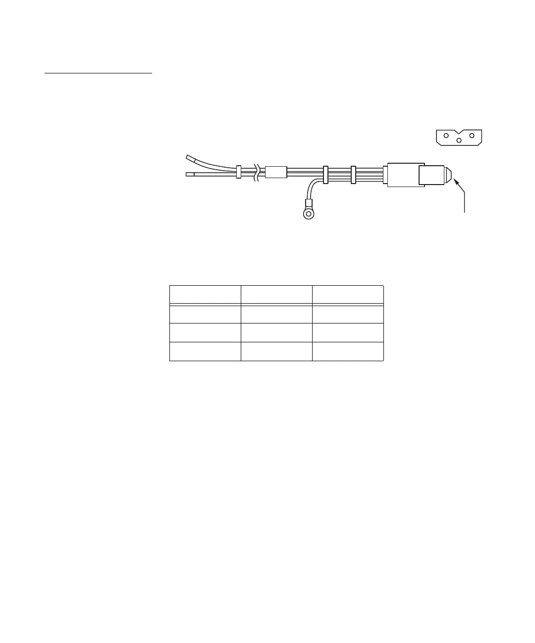
Figure 1 shows the power cord provided by EMC for DC-powered disk processor
enclosures, DAEs, and control station inverters. Table 5 describes the pin outs.
Figure 1 DPE/DAE power cord
21
P1
3
P1
Positronic
CL4928
Table 5 Cabling pinout (Positronics)
P1 designation Description Wire color
1 DC positive (+) Black
2 DC negative (-) Brown
3 Chassis ground Green/Yellow

 Loading...


