EMC® VNX5300™ Hardware Information Guide
14
EMC® VNX5300™ Hardware Information Guide
Control Station switch and LEDs
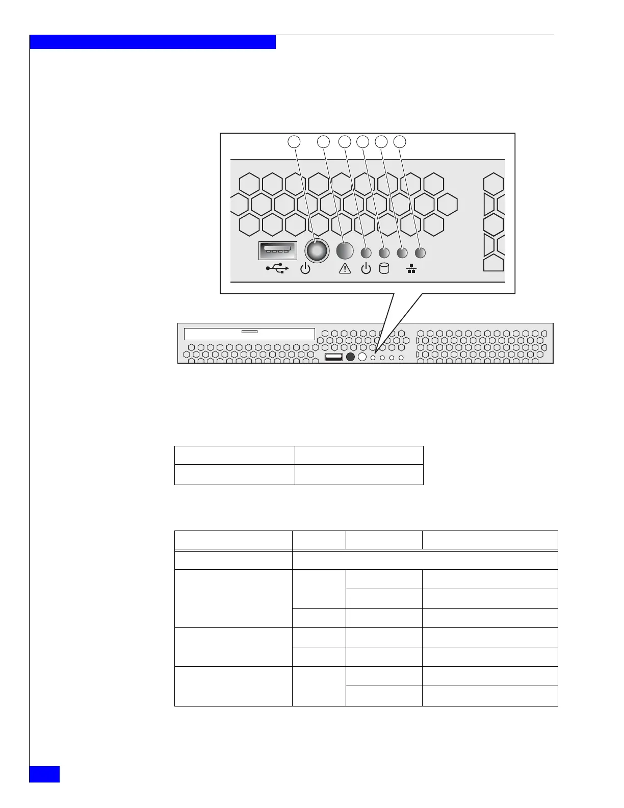
Figure 7 shows the location of the Block and File VNX5300 platform Control Station
switch and LEDs on the front panel. Table 4 describes the switch located on the front
panel. Table 5 describes the LEDs located on the front panel.
Figure 7 VNX5300 platform Control Station switch and LEDs
12
21 3 4 5 6
CNS-001744
Table 4 Control Station switch
Switch Description
Power push-button (location 1) Toggles the Control Station power
Table 5 Control Station LEDs
LED Color State Description
System status (location 2) Not used
System power/sleep (location 3) Green On Power on
Blinking Sleep
—Off Power off
Internal hard drive activity
(location 4)
Green Blinking Hard drive access
— Off No hard drive activity
Onboard (integrated) Ethernet
NIC 1 and 2 (locations 5 and 6,
respectively)
Green On NIC link/no access
Blinking NIC link/LAN access


 To Next Page