EMC® VNX5300™ Hardware Information Guide
16
EMC® VNX5300™ Hardware Information Guide
Power supply/cooling (fan) module LED
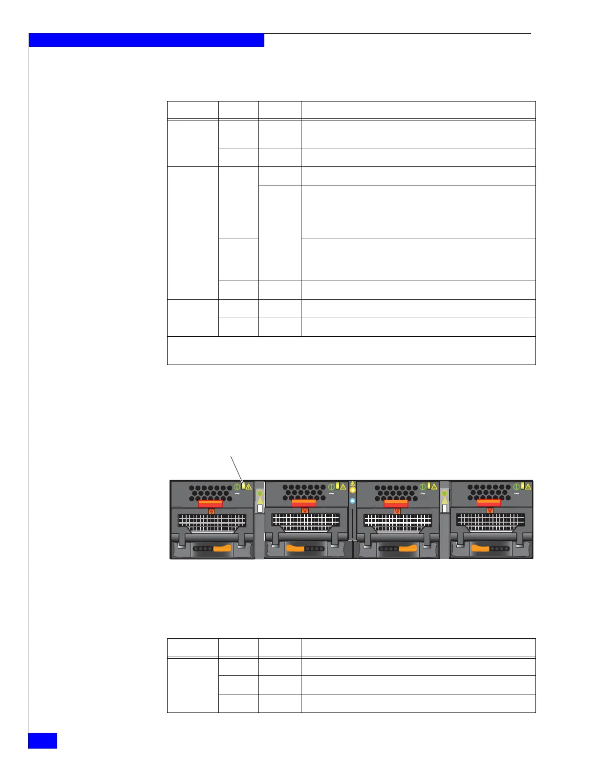
The power supply/cooling (fan) modules have a status LED on the front. Figure 10
shows the LEDs for the power supply/cooling (fan) modules and Table 8 describes
them.
Figure 10 Power supply/cooling (fan) module LED
Table 7 CPU LEDs
LED Color State Description
Power Green On Data Mover is powered up and all FRUs in the Data Mover are
operating properly.
— Off Data Mover is powered down.
Fault Amber On Data Mover has faulted.
Blinking Data Mover goes through six stages of power up:
1. Executes a BIOS check, blinking once every 4 seconds
2. Executes a POST check, blinking once every second
3. Loads the operating system, blinking four times a second
Blue (see
Note)
4. Operating system loaded, blinking once every 4 seconds
5. Operating system starting drivers, blinking once every second
6. Operating system drivers operating, blinking four times a second
— Off Data Mover operating normally.
Unsafe-to-
remove
White On Data Mover is unsafe to remove.
— Off Data Mover is safe to remove.
Note: The fault LED changes color from amber to blue when the operating system is loading, see step 4 in the
description.
AC
AC
AC
AC
Power supply/
cooling (fan) power/fault LED
CNS-001673
Table 8 Power supply/cooling (fan) module LED
LED Color State Description
Power/Fault Green On Normal (no faults detected)
Amber Blinking Power supplied but external fault detected
Amber On No power


 To Next Page