4
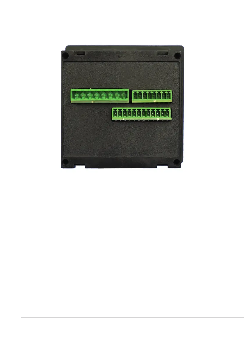
Mainboard Connections JACD and JACD PRO series
Unplug controller from main power supply then perform connections by following the picture below.
DC Version Model:
1(-) - 2(+): 12 or 24VDC (see controller’s label)
AC Version Model:
L(Live) - N(Neutral): 85÷264VAC or 18÷36VAC 50/60 Hz (see controller’s label)
3(Common) - 4(N.O.): Setpoint 1 Output (free contact output max 2A)
5(Common) - 6(N.O.): Setpoint 2 Output (free contact output max 2A)
7(Common) - 8(N.O.): Alarm Output (free contact output max 2A)*
9(-) - 10(+): Standby contact*
11(-) - 12(+): Opto coupled output NPN PULSE. To use with “IS” , “MF” , “PLUS” series pumps (max 50mA / 24VDC)*
13(GND) - 14(- Blue) - 15(Black) - 16(+ Brown): Proximity sensor mod. “SEPR” (dont’ remove jumper on blocks 13 and 14)
17(- RS485) - 18(+ RS485): RS485 (Modbus / Communication)*
19 (OUT Red) - 20 (IN Black) - 21(GND): Conductivity probe input
23(Green) - 24(Brown) - 25(White) - 26(Yellow): PT100 temperature probe (remove jumper / resistor when probe is installed)
27(+) - 28(-): mA Current Output (Max resistive load: 500Ohm)
Warning: Connections must be performed by qualified and trained personnel only
*Some functions aren’t available on standard models (see page 25)
L1 N2 3 4 5 6 7 8
9 10 11 12 13 14 15 16
17 18 19 20 21 22 23 24 25 26 27 28