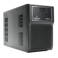
The operator control panel is divided into three functional areas;
‘Mimic indications’, Control switches’, and ‘LCD display panel’.
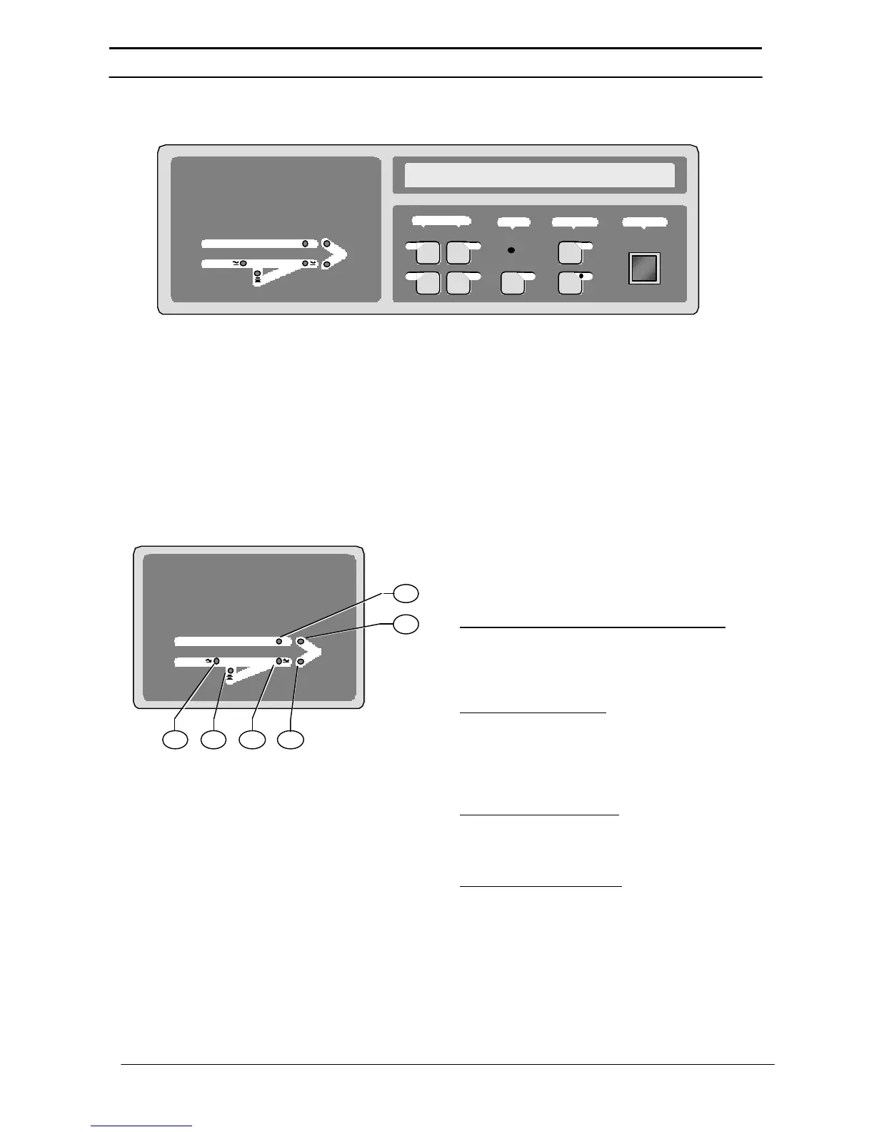
Mimic Indications
Six LEDs are mounted on a single line
diagram to represent the various UPS
power paths. These LEDs, which are
annotated in figure7, show the current UPS
operational status and should be
interpreted as detailed below.
LSI - Input supply OK / Rectifier operative:
This led illuminates when the input isolator
(I1) is closed, the input supply is within 20%
of nominal voltage, and the rectifier is
operative.
LS2 - Battery volts OK:
This led illuminates when the battery circuit
breaker is closed and the battery voltage is
within the UPS operating range - 320V-
432V nominal. (330V - 445V* nominal for
the 80 to 125 kVA Models).
LS3 - Bypass supply OK:
This led illuminates when the static bypass
supply in within 10% of its nominal voltage
and the static bypass isolator is closed.
LS4 - Inverter-output OK:
This led illuminates when the inverter is
operating and its output is within a preset
acceptable voltage window.
Uninterruptible Power System
=
=
ALARM
MEASUREMENTS
INVERTER EMERGENCY
Vo
f
Io
B ON
OFF
((•))
 Loading...