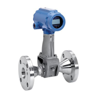
Rosemount Model 8800C Smart Vortex Flowmeter
2
SECTION 3
Operation
Review . . . . . . . . . . . . . . . . . . . . . . . . . . . . . . . . . . . . . . . . . . . . . . . . 3-1
Process Variables. . . . . . . . . . . . . . . . . . . . . . . . . . . . . . . . . . . . . . . . 3-1
Totalizer . . . . . . . . . . . . . . . . . . . . . . . . . . . . . . . . . . . . . . . . . . . . 3-2
Diagnostics/Service . . . . . . . . . . . . . . . . . . . . . . . . . . . . . . . . . . . . . . 3-3
Test/Status . . . . . . . . . . . . . . . . . . . . . . . . . . . . . . . . . . . . . . . . . . 3-3
Loop Test. . . . . . . . . . . . . . . . . . . . . . . . . . . . . . . . . . . . . . . . . . . . 3-3
Pulse Output Test. . . . . . . . . . . . . . . . . . . . . . . . . . . . . . . . . . . . . 3-3
Flow Simulation . . . . . . . . . . . . . . . . . . . . . . . . . . . . . . . . . . . . . . 3-3
D/A Trim . . . . . . . . . . . . . . . . . . . . . . . . . . . . . . . . . . . . . . . . . . . . 3-5
Scaled D/A Trim . . . . . . . . . . . . . . . . . . . . . . . . . . . . . . . . . . . . . . 3-5
Shed Freq at URV. . . . . . . . . . . . . . . . . . . . . . . . . . . . . . . . . . . . . 3-5
Basic Setup. . . . . . . . . . . . . . . . . . . . . . . . . . . . . . . . . . . . . . . . . . . . . 3-5
Tag. . . . . . . . . . . . . . . . . . . . . . . . . . . . . . . . . . . . . . . . . . . . . . . . . 3-5
Service Type . . . . . . . . . . . . . . . . . . . . . . . . . . . . . . . . . . . . . . . . . 3-5
PV Units . . . . . . . . . . . . . . . . . . . . . . . . . . . . . . . . . . . . . . . . . . . . 3-6
Range Values . . . . . . . . . . . . . . . . . . . . . . . . . . . . . . . . . . . . . . . 3-10
Process Temperature . . . . . . . . . . . . . . . . . . . . . . . . . . . . . . . . . 3-10
Mating Pipe ID (Inside Diameter). . . . . . . . . . . . . . . . . . . . . . . 3-11
Damping . . . . . . . . . . . . . . . . . . . . . . . . . . . . . . . . . . . . . . . . . . . 3-11
Advanced Functionality. . . . . . . . . . . . . . . . . . . . . . . . . . . . . . . . . . 3-12
Detailed Set-Up . . . . . . . . . . . . . . . . . . . . . . . . . . . . . . . . . . . . . . . . 3-12
Characterize Meter. . . . . . . . . . . . . . . . . . . . . . . . . . . . . . . . . . . 3-12
PV Units . . . . . . . . . . . . . . . . . . . . . . . . . . . . . . . . . . . . . . . . . . . 3-14
Configure Options. . . . . . . . . . . . . . . . . . . . . . . . . . . . . . . . . . . . 3-14
HART Output . . . . . . . . . . . . . . . . . . . . . . . . . . . . . . . . . . . . . . . 3-17
Signal Processing . . . . . . . . . . . . . . . . . . . . . . . . . . . . . . . . . . . . 3-20
Device Information. . . . . . . . . . . . . . . . . . . . . . . . . . . . . . . . . . . 3-23
SECTION 4
Hardware and Software
Maintenance and
Troubleshooting
Safety Messages. . . . . . . . . . . . . . . . . . . . . . . . . . . . . . . . . . . . . . . . . 4-1
Troubleshooting Tables . . . . . . . . . . . . . . . . . . . . . . . . . . . . . . . . . . . 4-3
Advanced Troubleshooting . . . . . . . . . . . . . . . . . . . . . . . . . . . . . . . . 4-6
TP1 . . . . . . . . . . . . . . . . . . . . . . . . . . . . . . . . . . . . . . . . . . . . . . . . 4-7
Shedding Frequency Out . . . . . . . . . . . . . . . . . . . . . . . . . . . . . . . 4-9
Testing procedures. . . . . . . . . . . . . . . . . . . . . . . . . . . . . . . . . . . . . . . 4-9
Hardware Replacement. . . . . . . . . . . . . . . . . . . . . . . . . . . . . . . . . . 4-10
Replacing the Terminal Block in the Housing . . . . . . . . . . . . . 4-11
Replacing the Electronics Boards . . . . . . . . . . . . . . . . . . . . . . . 4-12
Replacing the Electronics Housing . . . . . . . . . . . . . . . . . . . . . . 4-13
Replacing the Sensor . . . . . . . . . . . . . . . . . . . . . . . . . . . . . . . . . 4-15
Replacing the Sensor: Removable and
Integral Support Tubes . . . . . . . . . . . . . . . . . . . . . . . . . . . . . . . 4-17
Remote Electronics Procedure. . . . . . . . . . . . . . . . . . . . . . . . . . 4-22
Coaxial Cable at the Electronics Housing. . . . . . . . . . . . . . . . . 4-25
Changing the Housing Orientation . . . . . . . . . . . . . . . . . . . . . . 4-26
Return of Material. . . . . . . . . . . . . . . . . . . . . . . . . . . . . . . . . . . . . . 4-27
 Loading...


