•
3-in 3-out, split-bypass configuration
1. Remove all the shorted copper bars 3 from the UPS I/O terminal block.
2. Connect the live line (mains phase A, mains phase B and mains phase C), N line and PE line respectively to the
I/O terminal block (mA, mB, mC and mN terminals) and PE terminals of the UPS.
3. Connect the live line (bypass phase A, bypass phase B and bypass phase C), N line and PE line respectively to bA,
bB, bC and bN terminals of the UPS I/O terminal block.
4. Connect the live line (output phase A, output phase B and output phase C), N line and PE line respectively to the
I/O terminal block (oA, oB, oC and oN terminals) and PE terminals of the UPS.
•
3-in 1-out, common source configuration
1. As shown in Figure 2-10, you can paste the insulating film (accessory) to the shorted copper bar 10, and insert the
buckles into the corresponding holes on the shorted copper bar 10.
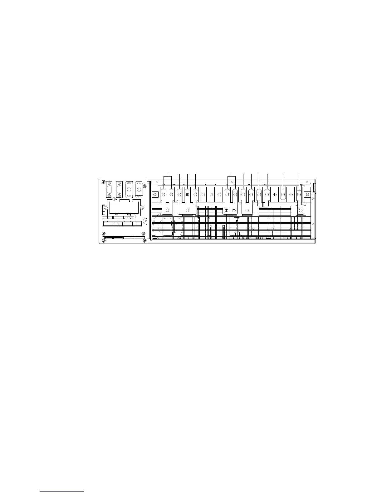
2. As shown in Figure 2-13, you can short two PE terminals of the UPS I/O terminal block using the shorted copper
bar 10 with an insulating film, short bA, bB and bC terminals using the shorted copper bar 7, short oA, oB and oC
terminals using the shorted copper bar 5, and short mA and bA terminals using the shorted copper bar 6 and then
short mN and bN terminals, two oN terminals using two shorted copper bars 4.
oN
oA oB oC
PE
mN
bN mA bA bB
bC
7
6
8
4 5 10
4
Figure 2-13 Shorted copper bars connection for UPS I/O terminal block
3. Connect the shorted copper bar 8 to one end of the shorted copper bar 7 (see Figure 2-13), and connect the live
line (input phase A) to the shorted copper bar 8.
4. Connect the live line (input phase B and input phase C), N line, PE line respectively to the I/O terminal block (mB
and mC terminals), shorted copper bar 4 of mN and bN terminals, and one screw hole of shorted copper bar 10 of the
UPS.
5. Connect the live line (output phase A), N line and PE line respectively to the shorted copper bar 5 of the I/O
terminal block, shorted copper bar 4 of two oN terminals and the other screw hole of shorted copper bar 10 of the
UPS.
•
3-in 1-out, split-bypass configuration
1. As shown in Figure 2-10, you can paste the insulating film (accessory) to the shorted copper bar 10, and insert the
buckles into the corresponding holes on the shorted copper bar 10.
2. Short two PE terminals of the UPS I/O terminal block using the shorted copper bar 10 with an insulating film, short
bA, bB and bC terminals using the shorted copper bar 7, and short oA, oB and oC terminals using the shorted copper
bar 5, and then short mN and bN terminals, two oN terminals using two shorted copper bars 4, as shown in Figure
2-14.