20
EN Drive Installation Manual
Motor Feedback Wiring
Encoder feedback connections are made with the CFCS cable. This cable has an MS style
connector on the motor end and a 26-pin high density “D” connector on the drive end.
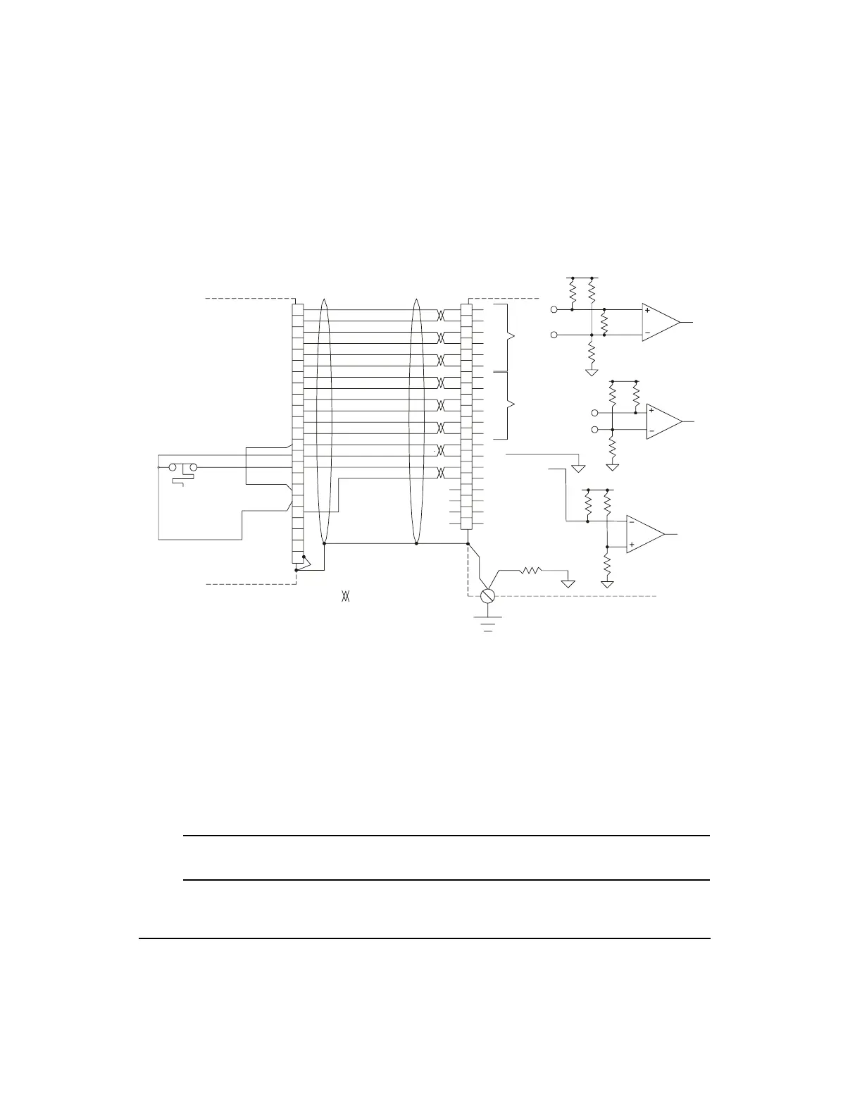
Figure 15: Motor Feedback Connector Pinout
Connection of encoder commutation signals to the drive
EN drives with a part number of 960500-08 or higher (part number label is located on the top
of the drive by the AC Input connector) are capable of receiving U, V and W commutation
signals from either a differential or common-collector source. Figure 15 shows the input
impedance for the U, U/, V, V/, W and W/ inputs on the drive. For single-ended encoder
outputs, leave U/, V/, and W/ unconnected at the drive.
EN drives with a part number of 960500 -07 or lower can only accept differential U,V,W,
signals.
Note
The indexing pulses A, A/, B, B/, Z, and Z/ must come from a differential source.
Motor
Motor Feedback Cable
Model # CFCS-XXX
Blue
Orange
Green
Brown
Black
Yell ow
White/Brown
Brown/White
White/Gray
Gray/White
Red/Orange
Orange/Red
*Red/Blue
Blue/Red
Red/Green
Green/Red
13
15
17
16
1
10
11
2
3
12
4
5
14
6
7
9
8
18
19
26
R
H
T
J
B
C
P
N
M
U
E
F
S
G
K
A
L
D
V
W
U/
W/
A
A/
B/
B
Z
Z/
U
V
V/
W
+ 5 VDC
+ 5 VDC
Shield
X
Y
Z
Connector Shell
Internal
Motor
Thermal
Switch
GND
Motor
Overtemp
Overtemp GND
* The “+5 VDC (18AWG) wire
will be colored “Red/Green”
on some CFCS cables.
= Twisted Pair
Single Point
Ground
Drive
U/
W/
A
A/
B/
B
Z
Z/
U
V
V/
W
Not Used
GND
+5 VDC
GND
Motor Overtemp
+ 5VDC
GND
19 to 24 PE Ground
100K
A/
+5 V
100K
220 Ohm
100K
A
2K
U/
+5 V
2K
U
1K
10K
+5 V
10K
1.0K
10 Ohm
PE
Artisan Technology Group - Quality Instrumentation ... Guaranteed | (888) 88-SOURCE | www.artisantg.com
 Loading...