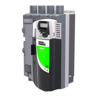
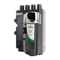
Do you have a question about the Emerson Quantum MP and is the answer not in the manual?
Explains warning, caution, and note symbols for safe operation.
General warnings about severe electrical shock and lethal voltages from the drive.
Drive installation requires professional assemblers, careful consideration of hazards, and risk analysis.
Compliance with specified environmental limits for transport, storage, installation, and use.
Access restriction to authorized personnel and compliance with local safety regulations.
The drive enclosure is not a fire enclosure; a separate one must be provided.
Installer's responsibility to comply with national wiring, accident prevention, and EMC regulations.
Motor installation must follow recommendations; parameter values affect motor protection.
Parameters with profound operational effects require careful consideration to prevent unwanted changes.
Details on electric shock risks from various locations and stored charge within the drive.
Describes the components that make up the Quantum MP drive system.
Provides power ratings, continuous current ratings, and derating information for 480V configurations.
Explains how maximum overload limits change based on motor selection and provides a chart.
Details the format and composition of the Quantum MP drive model numbers.
Lists encoders compatible with the Quantum MP drive and their corresponding parameter settings.
Explains the information found on the drive rating label for size 1 and size 2 Quantum MP drives.
Illustrates and lists the features and optional modules available for the Quantum MP drive.
Details various Solutions Modules for feedback and I/O expansion, their colors, names, and further details.
General safety instructions and warnings related to mechanical installation of the drive.
Key considerations for planning the installation, including access, environmental protection, and cooling.
Instructions for removing terminal covers, including warnings about stored charge and isolation.
Details on how the Quantum MP drive can be surface mounted, including dimensions and mounting points.
Information on enclosure layout and sizing considerations for proper drive installation.
Explanation of how the drive's heatsink fan operation is controlled based on temperature.
Refers to section 12.1.11 for an explanation of IP Rating and its meaning.
Details the location of power and ground terminals, and provides terminal sizes and torque settings for Size 1 drives.
Details the location of power and ground terminals, and provides terminal sizes and torque settings for Size 2 drives.
Recommendations for routine checks to ensure drive and installation reliability, covering environment, enclosure, and electrical connections.
Explains AC and DC connections, referring to diagrams for size 1 and size 2 drives.
Instructions for connecting the drive to the AC supply system ground, including warnings and impedance considerations.
Details the standard drive rating for nominal supply voltage and acceptable supply types.
Recommends external line inductance to mitigate disturbances from voltage notches caused by SCR drives.
Explains the auxiliary AC supply and its connections, including terminal functions.
Steps for powering the auxiliary supply from a separate source, including safety precautions.
Details the onboard 120 Vac power source, its transformer connections, and protection.
Explains the three main functions of the 24 Vdc input supply.
Guidance on selecting fuses and cabling, considering continuous currents and installation regulations.
Details the drive's internal suppression and facility for extra suppression using external resistors.
Information on ground leakage current and the use of residual current devices (RCDs).
Overview of Quantum MP's EMC immunity requirements and measures for radio frequency noise emission.
Details the drive's serial port, RJ45 connector, and communication protocols (EIA485, EIA232).
Instructions for connecting cable shields to ensure radio frequency emission suppression and noise immunity.
General overview of control connections, consisting of various input/output parameters and their terminal numbers.
Details specifications for 120V User I/O control terminal and 24 Vdc/Analog control terminal.
Additional measures for radio frequency emission prevention when connecting encoders, including shielding.
Describes the two available keypad types (SM-Keypad LED and SM-Keypad Plus LCD) and their displays.
Explains the components of the keypad and how to navigate parameters and control the drive.
Details accessing Menu 0 via sub block mode and keypad navigation for pre-defined sub blocks.
Lists and describes the pre-defined sub blocks available for drive setup and parameter access.
Explains how Menu 0 brings together commonly used parameters for basic drive setup.
Describes the drive's parameter structure consisting of menus and parameters, and how navigation works.
Introduces advanced menus containing groups of parameters for specific drive functions.
Procedure for saving parameter changes made in advanced menus, as they are not automatically saved.
Method to restore default parameter values, including steps for SMARTCARD or manual reprogramming.
Function to filter visible parameters to only show those with non-default values.
Function to filter visible parameters to only show destination parameters.
Determines user access to menus and security levels for read/write operations.
Details the drive's serial port, RJ45 connector, and communication protocols (EIA485, EIA232).
Provides detailed descriptions of parameters found in pre-defined sub blocks for basic drive setup.
Step-by-step guide for initial drive commissioning and setup using default USA parameters.
Step-by-step guide for initial drive commissioning and setup using default European parameters.
Information on using CTSoft for drive commissioning, monitoring, and parameter management.
Detailed information on parameter settings for compatible encoder types for Quantum MP.
Guidance on setting motor rated current and current limits for armature current control.
Explains different methods for setting up speed feedback: estimated, tachometer, encoder, and Solutions Module.
Setting the rated field current and voltage for the field controller, and enabling field weakening.
Procedures for self-tuning current loop gains to optimize drive performance based on motor characteristics.
Tuning proportional (Kp), integral (Ki), and differential (Kd) gains for optimal speed controller response.
Using current limit tapers to provide speed-dependent current limits for motor commutation.
Explains the SMARTCARD feature for parameter configuration, saving, and loading.
Describes SMARTCARD data block locations and usage for saving and reading parameter sets.
Explains how to transfer data between the drive and SMARTCARD using parameter codes in Pr xx.00.
Details the information contained in each data block header on the SMARTCARD.
Lists parameters related to SMARTCARD operation, including data block numbers, types, and versions.
Lists SMARTCARD trip indications and their corresponding conditions and diagnostic information.
Introduces the Quantum MP's onboard PLC capability and SYPT Lite software for ladder logic programming.
Highlights the advantages of using the Onboard PLC and SYPT Lite for replacing smaller PLCs.
Outlines the limitations of the Onboard PLC program compared to SM-Applications Plus or Lite modules.
Information on obtaining and installing SYPTLite, including system requirements.
Lists parameters associated with the Onboard PLC program, specifically for enabling and controlling it.
Lists trips associated with the Onboard PLC program and their diagnostic information.
Explains how to transfer Onboard PLC programs between the drive and a SMARTCARD.
Controls the main speed reference selection, including analog, preset, keypad, and precision references.
Manages ramp blocks for speed control, including linear and S-ramp functions for acceleration and deceleration.
Details speed accuracy, resolution, and options for setting up speed feedback and control.
Parameters for controlling motor torque and armature current, including limits and overload protection.
Settings related to motor and field control, including back EMF, armature voltage, and field weakening.
Configuration for sequencer logic, digital inputs, and clock functions for drive control.
Configuration and scaling for analog inputs and outputs, including invert and destination parameters.
Configuration of digital inputs and outputs, including state, invert, source, and destination settings.
Settings for programmable logic, motorized potentiometers, and binary sum functions for custom control.
Displays drive status, alarms, and trip indications, with detailed lists of trips and their diagnoses.
General drive setup parameters, including serial communications, security, and SMARTCARD settings.
Advanced features for threshold detection, variable selection, and brake control logic.
Configuration for position control, including reference sources, feedback, and orientation.
Setup and configuration of the User PID controller for advanced control loops.
Information on installing and configuring Solutions Modules in different drive slots.
Parameters for Application Menu 1, including power-down saved and read-write settings.
Parameters for Application Menu 2, including power-down saved and read-write settings.
Parameters for Application Menu 3, including read-write integer and long integer settings.
Parameters for a second motor, including reference clamps, acceleration, deceleration, and current limits.
Parameters for setting up additional Menu 0 options.
Parameters for selecting sub-block headers and pre-defined sub-block enables.
Information on advanced drive functions like reference modes, S-ramps, and torque modes.
Comprehensive technical specifications for the Quantum MP drive, including ratings, power, and supply requirements.
Guidance on selecting fuses and cabling, considering continuous currents and installation regulations.
Information on sourcing optional EMC filters from Schaffner and Epcos.
Provides derating curves for Quantum MP drives based on ambient temperature.
Explains how trip indications are displayed, listed alphabetically, and cross-referenced with trip numbers.
Groups trips into categories for easier identification of issues and their priority.
Lists common alarms and their associated conditions, including actions to take to prevent tripping.
Displays the drive's operational status, such as decelerating, inhibited, ready, running, or tripped.
Shows how to view the last 10 trips that have occurred, using specific parameters.
Describes how the drive behaves when tripped and which parameters remain frozen for diagnosis.
General UL conformity requirements, including enclosure type, ambient temperature, terminal torques, and wiring.
Specifies the maximum UL supply voltage and circuit capability.
Lists the maximum continuous output currents for different drive models as shown in Chapter 2.2.
Instructions on placing the safety label and its content regarding electric shock precautions.
Lists accessories that are UL listed for use with the Quantum MP drive.
| Control Method | Digital microprocessor-based control |
|---|---|
| Communication Options | Ethernet, Profibus, DeviceNet |
| Enclosure Type | NEMA 1, NEMA 12 |
| Cooling Method | Air-cooled, Liquid-cooled (for higher HP models) |
| Protection Features | Overcurrent, overvoltage, undervoltage, overtemperature, short circuit |


