Safety
Information
Product
Information
Mechanical
Installation
Electrical
Installation
Getting
Started
Basic
parameters
Running the
Motor
Optimization
SMARTCARD
Operation
Onboard
PLC
Advanced
Parameters
Technical
Data
Diagnostics
UL
Information
Quantum MP User Guide 37
Issue: A4 www.emersonct.com
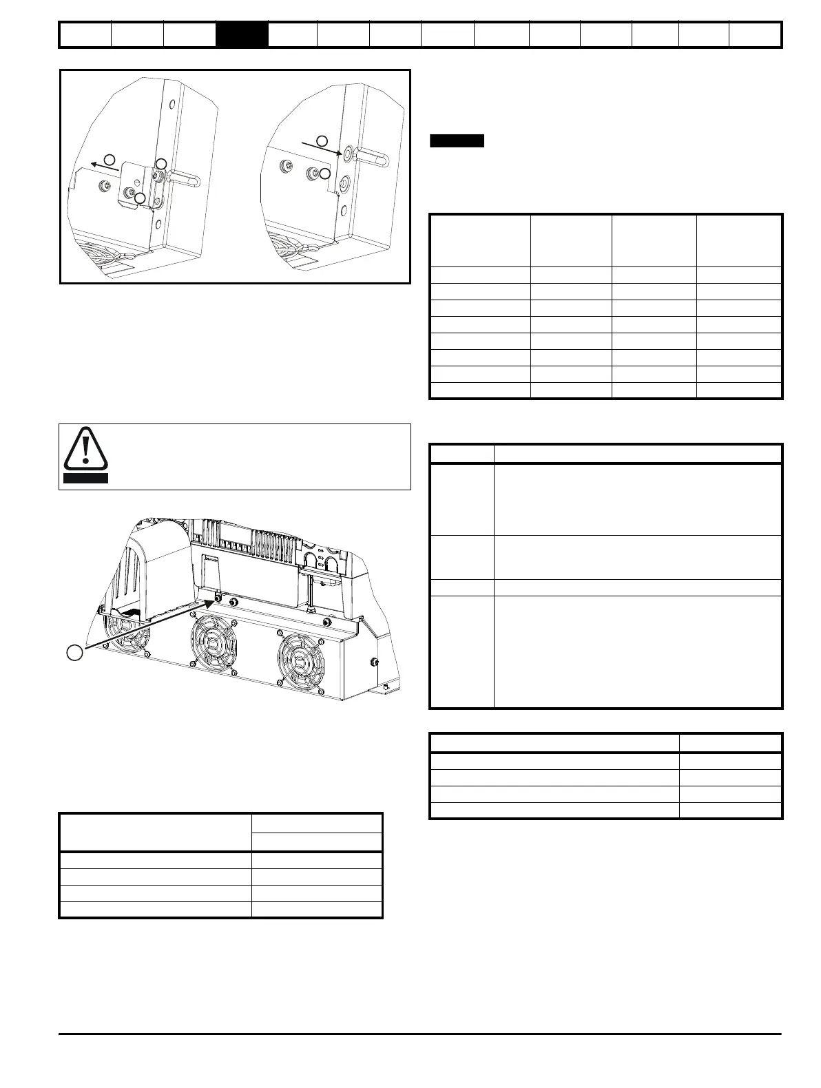
Figure 4-7 Removing the MOV ground connection, Size 1
The method for disconnecting the MOV ground connection is shown
below:
1. Remove the M4 x 16 screw using T20 Torx driver.
2. Remove the M4 x 12 screw using T20 Torx driver.
3. Remove the plate.
4. Re-fit the M4 x 12 screw using T20 Torx driver and tighten to a
torque of 0.6 Nm (0.44 Ib ft).
5. Fit a M4 x 16 nylon screw (not supplied) and tighten to a torque of
0.25 Nm (0.18 Ib ft).
Figure 4-8 Removing the MOV ground connection, Size 2
The method for disconnecting the MOV ground connection is shown
below:
1. Remove the M4 x 30 screw using T20 Torx driver
If re-fitting the M4 x 30 screw using T20 Torx driver, the screw must be
tightened to a torque of 2.5Nm (1.84 lb ft).
4.3.3 SCR bridge AC supply
Table 4-1 Three phase AC supply
4.4 Line reactors
The Quantum MP, in common with all naturally commutated SCR drives,
causes voltage notches at the input supply terminals. In order to avoid
disturbance to other equipment using the same supply, the addition of
external line inductance is strongly recommended in order to restrict the
depth of the notches imposed on the shared supply. This is generally not
necessary where a dedicated transformer is used to supply the drive.
The following recommendations for added line inductance, have been
calculated based on the power drive systems standard: EN61800-
3:2004 “Adjustable speed electrical power drive systems – Part 3: EMC
requirements and specific test methods”.
The current ratings specified in Table 4-2 is for typical motor currents
where the motor current ripple is no more than 50% of drive rating.
Table 4-2 Minimum values of L
add
and inductor current rating -
480V supply
4.5 Auxiliary AC supply and connections
Table 4-3 Terminal functions
Table 4-4 One phase line to line supply
Each drive has an on-board field controller with the following current
ratings.
The M4 x 16 screw (1) should not be re-used if the plate (3)
is not re-installed. Instead a nylon screw should be used.
Specification
Product voltage variant
480V
Max nominal supply 480V
Tolerance +10%
Min nominal supply 24V
Tolerance -20%
Model
L
add
Typical
current rating
Maximum
current rating
µH A A
QMP45A4(R) 260 38 40
QMP75A4(R) 260 63 67
QMP155A4(R) 190 130 139
QMP210A4(R) 140 176 188
QMP350A4(R) 85 293 313
QMP400A4(R) 71 351 375
QMP550A4(R) 54 460 492
QMP700A4(R) 43 586 626
Terminals Function
E1, E3
Supply for control electronics and field controller. These
terminals should be in phase with the mains supply to the
drive. E1 and E3 are pre-wired at the factory to the main
supply lines L1 and L3. If it is necessary to separate the
auxiliary and main supplies, see
section 4.6
L11, L12
Field on / off. When L11 and L12 are open the supply is
disconnected to the field regulator so there will be no field
current.
F+, F- Field supply to the motor.
MA1, MA2
These terminals are used to provide feedback from the
motor armature terminals. This is required when there is a
contactor in the main DC armature connection as is the
case with Quantum MP. When the contactor is opened
the drive will still be receiving armature feedback. This
allows the field regulator to function correctly when the
contactor is open. MA1 and MA2 are pre-wired at the
factory to the appropriate armature terminals.
Specification Value
Max nominal supply 480 V
Tolerance +10%
Min nominal supply 208 V
Tolerance -10%