Safety
Information
Product
Information
Mechanical
Installation
Electrical
Installation
Getting
Started
Basic
parameters
Running the
Motor
Optimization
SMARTCARD
Operation
Onboard
PLC
Advanced
Parameters
Technical
Data
Diagnostics
UL
Information
100 Quantum MP User Guide
www.emersonct.com Issue: A4
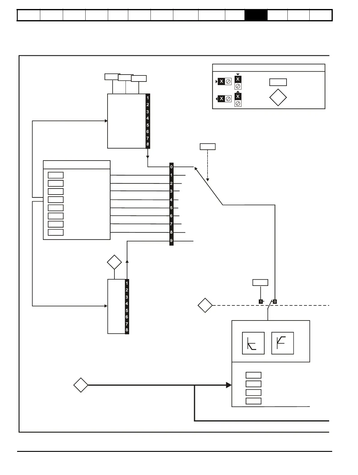
11.2 Menu 2: Ramps
The pre-ramp speed reference passes through the ramp block controlled by menu 2 before being used by the drive to produce input to the speed
controller. The ramp block includes: linear ramps, and an S ramp function for ramped acceleration and deceleration.
Figure 11-2 Menu 2 logic diagram
0 0 0
0 0 1
0 1 0
0 1 1
1 0 0
1 0 1
1 1 0
1 1 1
Acceleration rate select bits
2.11
Acceleration rate 1
2.12
Acceleration rate 2
2.13
Acceleration rate 3
2.14
Acceleration rate 4
2.15
Acceleration rate 5
2.16
Acceleration rate 6
2.17
Acceleration rate 7
2.18
Acceleration rate 8
Acceleration rates 1 ~ 8
1.50
3
4
1
2
7
5
6
Preset reference
selected indicator
Reverse
accel. rate
Forward
accel. rate
2.33
2.32
0.XX
0.XX
Key
Read-write (RW)
parameter
Read-only (RO)
parameter
Input
terminals
Output
terminals
The parameters are all shown at their default settings
8