Safety
Information
Product
Information
Mechanical
Installation
Electrical
Installation
Getting
Started
Basic
parameters
Running the
Motor
Optimization
SMARTCARD
Operation
Onboard
PLC
Advanced
Parameters
Technical
Data
Diagnostics
UL
Information
106 Quantum MP User Guide
www.emersonct.com Issue: A4
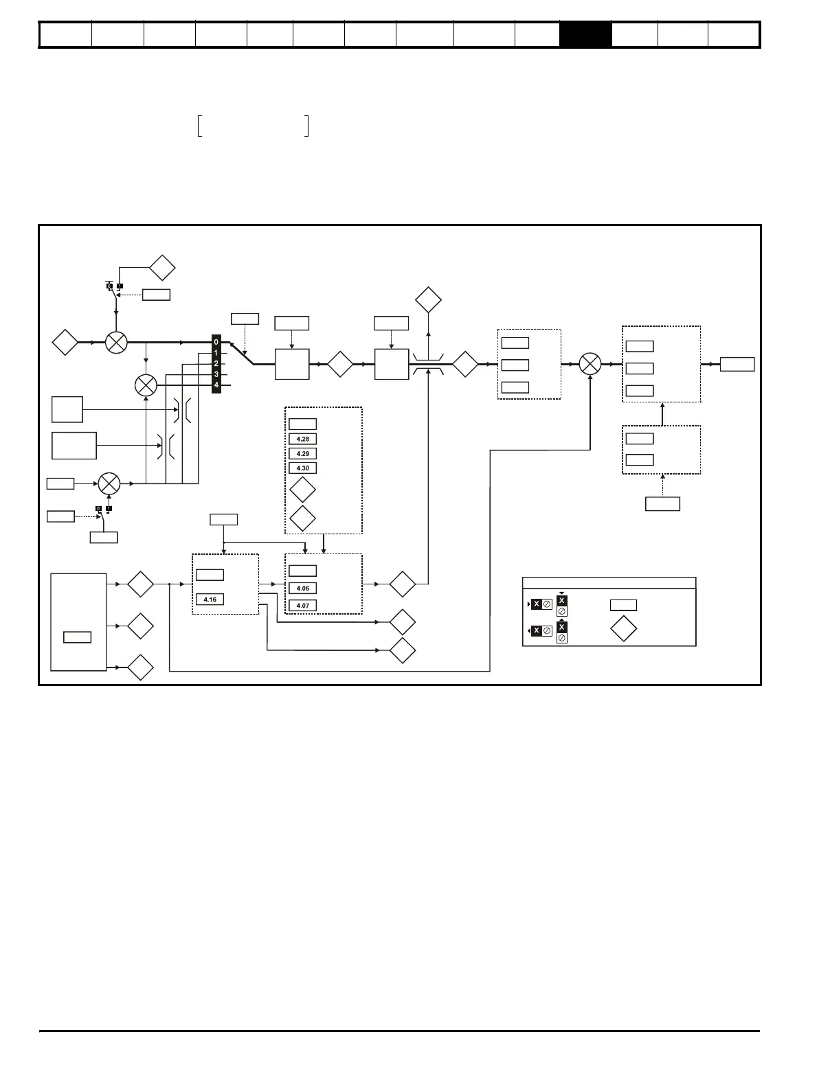
11.4 Menu 4: Torque and current control
MOTOR1_CURRENT_LIMIT_MAX is used as the maximum for some parameters such as the user current limits. The current maximum current limit
is defined as follows (with a maximum of 1000%):
Where:
Motor rated current is given by Pr 5.07 (SE07, 0.28)
(MOTOR2_CURRENT_LIMIT_MAX is calculated from the motor map 2 parameters). The maximum current is 1.5 x drive rating.
Figure 11-4 Menu 4 logic diagram
CURRENT_LIMIT_MAX
Maximum current
Motor rated current
-------------------------------------------------------
100%=
demand
+
_
3.04
4.08
4.09
10.09
5.07
4.05
Motoring
Regenerating
Current limits
Symmetrical
Motor rated
current
Speed loop
output
Torque reference
offset
Torque
reference
Speed
over-ride
level
Coiler/uncoiler
speed over-
ride level
+
Current limit
active
indicator
Menu 5
4.01
Torque mode
selector*
4.11
4.10
Torque
reference
offset
enable
+
+
+
4.03
Torque
demand
(RW)
parameter
Read-only (RO)
parameter
Input
terminals
Output
terminals
The parameters are all shown at their default settings
4.24
User current
max scaling
+
4.22
2.38
Inertia
compensation
enable
+
Inertia
compensation
torque
Torque to
current
conversion
limit
4.33
Menu 5
Quandrant
select
Continuous
Kp gain
4.13
Continuous
Ki gain
4.14
Discontinuous
Ki gain
4.34
Current
measurement
4.02
4.20
Percentage
load
Filtered current
magnitude
Current
magnitude
4.15
Thermal
time
constant
Thermal
protection
mode
Overload detection
4.18
10.17
4.19
indicator
Overriding
current limit
4.27
1 threshold
2 threshold
Current taper
1 end point
2 end point
4.31
4.32
Threshold 1
exceeded
Threshold 2
exceeded