Safety
Information
Product
Information
Mechanical
Installation
Electrical
Installation
Getting
Started
Basic
parameters
Running the
Motor
Optimization
SMARTCARD
Operation
Onboard
PLC
Advanced
Parameters
Technical
Data
Diagnostics
UL
Information
24 Quantum MP User Guide
www.emersonct.com Issue: A4
Table 3-5 Dynamic Braking Resistor (DB+ and DB-) terminals Table 3-6 Suppression Resistor (SR+ and SR-) terminals
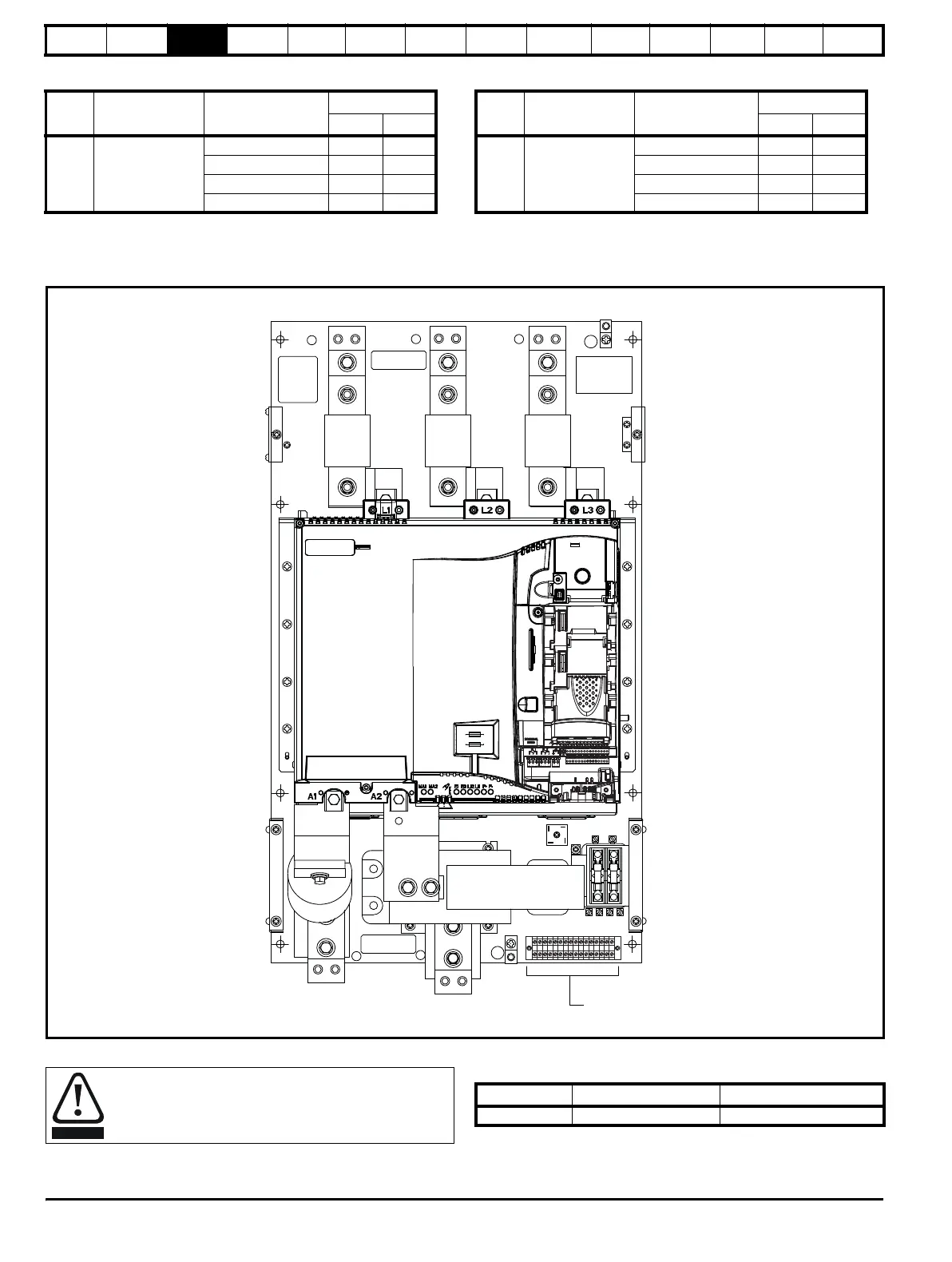
3.9 Electrical terminals - Size 2
3.9.1 Location of the power and ground terminals
Figure 3-12 Location of the power and ground terminals
3.9.2 Terminal sizes and torque settings 3.9.3 Torque settings
Table 3-7 Drive control, status relay and encoder terminal data
Model Connection type Wire gauge
Torque setting
Nm lb ft
All
Slotted lug
14-10 AWG 4 2.92
8 AWG 4.5 3.33
6-4 AWG 5 3.75
2 AWG 5.6 4.17
Model Connection type Wire gauge
Torque setting
Nm lb in
All
Slotted lug
14-10 AWG 4 2.92
8 AWG 4.5 3.33
6-4 AWG 5 3.75
2 AWG 5.6 4.17
L1
L2 L3
A+
A-
GND
GND
DANGER
HIGH VOLTAGE
DANGER
HIGH VOLTAGE
L1
L2 L3
GND
A2
A1
GND
120Vac Logic
Terminals
FIG 4A
To avoid a fire hazard and maintain validity of the UL listing,
adhere to the specified tightening torques for the power and
ground terminals. Refer to the following tables.
Model Connection type Torque setting
All
Plug-in terminal block 0.5 Nm 0.4 lb ft