176
Epsilon Eb and EN Drives Reference Manual
In this example, the parameters of two user defined motors are named “User1” and “User2”.
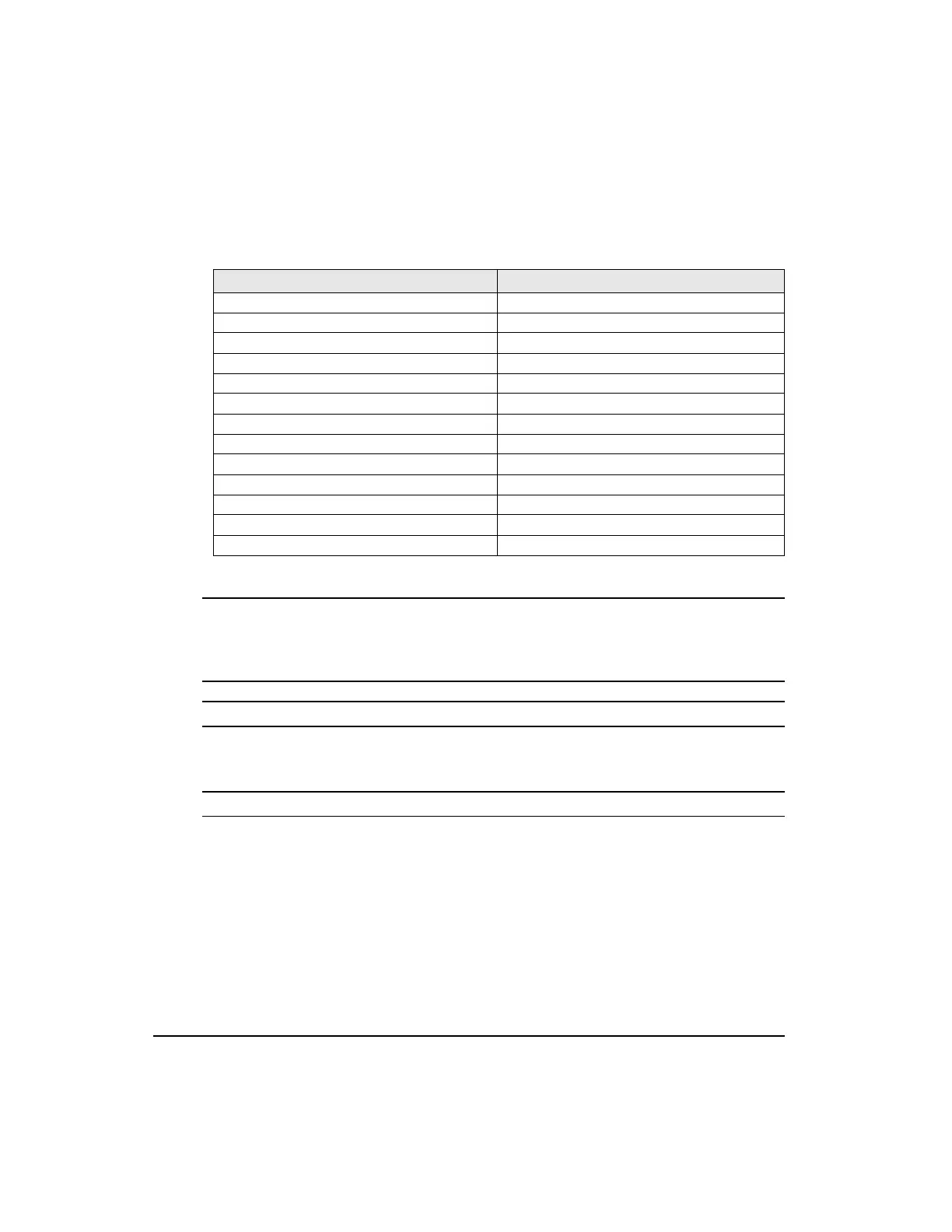
Abbreviated parameter identifiers are used in the .ddf file. The table below shows the
abbreviated identifier for each parameter followed by a description of each.
Motor Parameter Descriptions
Note
These parameters are valid and active only when a user defined motor is selected. When
an Control Techniques motor is selected, the data in these registers remain at the last value
set and do not update to reflect the data of the Control Techniques motor selected.
Motor Poles
Specifies the number of magnetic pole pairs (N-S) on the motor. The supported values are 2,
4, 6, 8, 10, 12, 14 and 16 poles.
Motor Encoder Lines Per Revolution
Specifies a coefficient for determining the number of encoder lines per mechanical
revolution. The supported values are 1 to 16383. The equation for determining the total
number of encoder lines per revolution is:
nLines = n*10
x
where
nLines = Total number of Encoder Lines
n = Motor Encoder Lines per Rev Coefficient
x = Motor Encoder Exponent
Motor Parameter DDF Identifier
Motor Poles motorPoles
Motor Encoder Lines Per Revolution encoderLines
Motor Encoder Marker Angle encoderMarker
Motor Encoder U Angle encoderU
Motor Encoder Reference Motion encoderRef
Motor Inertia rotorInertia
Motor KE motorKE
Motor Resistance phaseResistance
Motor Inductance phaseInductance
Motor Peak Current peakCurrent
Motor Continuous Current continuousCurrent
Motor Maximum Operating Speed maxOperatingSpeed
Motor Encoder Exponent encoderExponent
Artisan Technology Group - Quality Instrumentation ... Guaranteed | (888) 88-SOURCE | www.artisantg.com
 Loading...