CI-ControlWave EFM Appendix C - Hardware Installation Guide / C-5
A ControlWave EFM can be configured as a Master or Slave node on either a
MODBUS network or a BSAP network. Up to three communication ports are contained
on the ControlWave EFM CPU Module and are designated as follows:
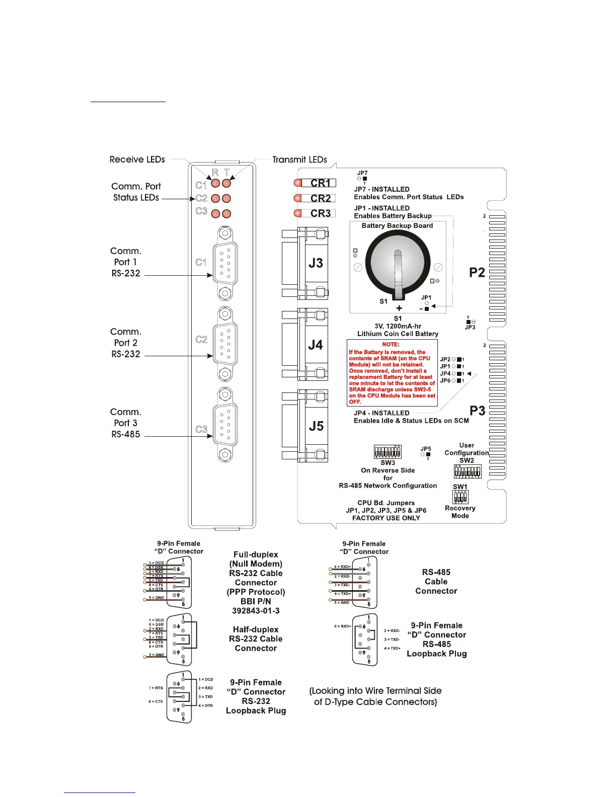
CPU Module:
COM1 - Port 1: CPU Bd. J3, PC/AT 9-Pin Male D-Sub - RS-232
COM2 - Port 2: CPU Bd. J4, PC/AT 9-Pin Male D-Sub - RS-232
COM3 - Port 3: CPU Bd. J5, PC/AT 9-Pin Male D-Sub - RS-485 - Supported by SW3
Figure C-3 - CPU Module Component Identification Drawing