CI-ControlWave EFM Appendix C - Hardware Installation Guide / C-11
Base Housings - Slots 3 & 4 (in lieu of Expansion Comm. Modules) & Slots 5 through 8
Expansion Housings - Any Slot
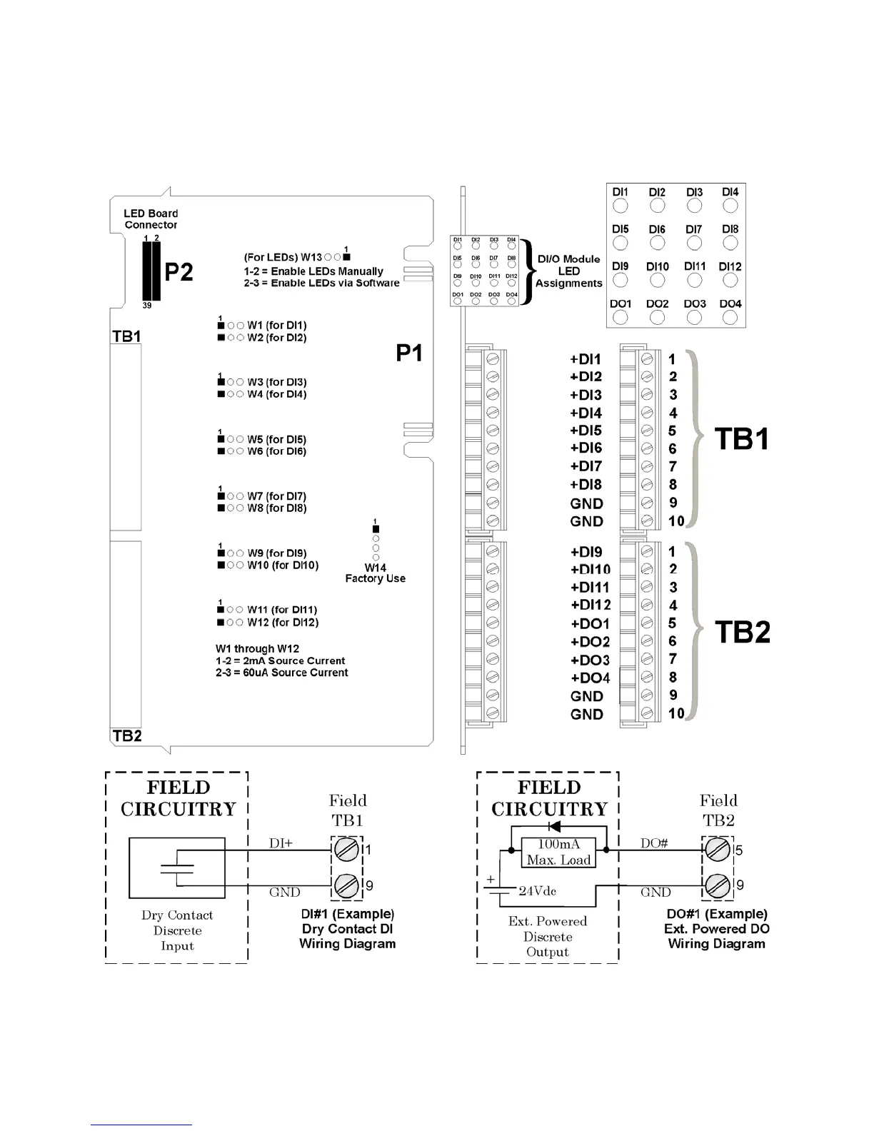
Install I/O wiring to each I/O Module (see Figures C-6 through C-10). Install a
communications cable between the ControlWave EFM and a Model 3808 Transmitter
(Network of Transmitters) if required (see Figures C-11 & C-12).
Figure C-6 - Non-Isolated DI/O Module Configuration Diagram