CI-CW MICRO/CW EFM Appendix D - Radio/Modem Installation Guide / D-5
Exp Comm. Module’s
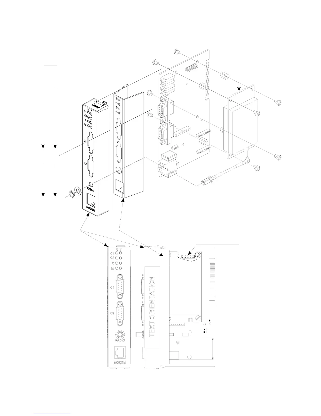
MDS Transnet Radio
Connector J11
If In Slot #3
Comm. Port
Assignments
If In Slot #4
N
TE:
ECOM Module Comm. Ports
4/8 (RS-232)
are wired the same as
CPU Module Comm. Ports
4/8
6/10
1
1
1
1
4
J11
3
3
3
3
1 = 6-32 x .188” Pan Head Screw (Qty. 4)
2 = x .313” F/F Standoff (Nylon) (Qty. 4)
3 = x .250” Pan Head Screw (Qty. 4)
4 = MDS Transnet Radio Cable (with Nut and Washer)
5 = MDS Transnet Radio Module
(Nylon)
6-32
6-32
MDS Transnet Radio Kit Parts
Cover Panel
EMI Gasket
MDS
Radio
module
Transnet
3
3
3
3
JP4
JP2
JP1
1
1
1
5
2
2
2
2
OPTION
Populated
by
Order
Figure D4 - MDS Transnet OEM Radio Installation Diagram