1-16 / Introduction CI-ControlWave EFM
The unit’s Base Assembly Chassis is mounted to the Fabrication Panel inside the Hoffman
Enclosure. ControlWave EFM Chassis’ contain a Ground Lug that accommodates up to a
#4 AWG Ground Wire. Grounding the unit is accomplished by connecting a ground wire
between the Ground Lug and a known good Earth Ground.
1.3.6 ControlWave EFM I/O Modules
Five unique I/O Modules are available factory configured for either local or remote field
device wiring termination. I/O Modules provide Configuration Jumpers that accommodate
individual field I/O user configuration. Terminations are pluggable and accept a maximum
wire size of 14 gauge. All I/O have surge protection that meets C37.90-1978 and IEC 801-5
specifications. Each I/O Module is connected to the ControlWave EFM Back-plane via a
36-pin male card-edge connector. With the exception of the Mixed Input/Output Module, all
I/O Modules are provided with two 10-point Terminal Block Assemblies (for local
termination) or two 14-pin Mass Termination Headers (for remote termination). Mixed I/O
Modules are provided with two 10-point Terminal Block Assemblies (for local termination).
A brief overview of each I/O Module type is provided below. Specifications are covered in
Section 4.4.
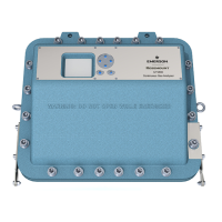
Figure 1-8 - Two ControlWave EFM I/O Modules (with Bezel)